
Install Instructions
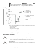
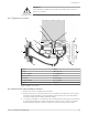
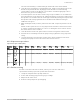
Table Of Contents

WARNING:
Pressurized device. Make sure that the internal pressure is relieved
before you continue.
11.Remove the volute capscrews and remove the pump assembly from the volute.
6.1.3 Typical cross section
1
6
5
10
7
8
2
13
9
4
12
11
6
10
3
14
1. Shaft 8. Volute
2. Slinger 9. Motor capscrew
3. Bracket coverplate 10. Gauge tapping
4. Volute capscrew 11. Suction
5. Discharge 12. Volute gasket
6. Companion flange 13. Seal assembly
7. Impeller 14. Jamnut
Figure 2: Typical cross section
6.1.4 Remove the seal assembly for all sizes
1. Remove the motor assembly from the system.
2. Remove the plug or cover from the motor rear end plate. This will allow access to the
end of the motor shaft. A slot or wrench flats are provided on the end of the shaft to
retain the shaft during assembly and disassembly.
3. Use a large screwdriver or an end wrench to hold the shaft socket and a socket wrench
to remove the jamnut. The jamnut is held in place with Loctite. Continue to hold the
shaft and turn the impeller counterclockwise to remove it from the motor shaft.
6 Maintenance
Series e-90 INSTRUCTION MANUAL 15