
Brochure


25
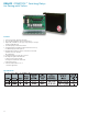
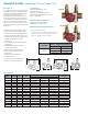
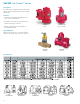
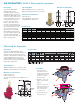
BALANCE VALVES Circuit Sentry
TM
Flo-Setter
TM
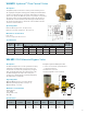
A
B
C
**
Includes tailpiece (not shown).
Measurement of maximum length
tailpiece available.
E
D
L
MAX
**
F
G
MAX
**
T
MAX
**
MODEL
NUMBER
PART
NUMBER
SIZE
CONNECTION
TYPE
DIMENSIONS
*
IN INCHES (mm)
FLOW CAPACITY IN GPM
(L/HR)
APPROX.
WEIGHT
lbs. (kg)
A B C D E MIN. MAX.
CS-1/2 117464 1/2"
NPT
Female
3.8
(97)
5.8
(147)
3.8
(97)
2.4
(61)
1.2
(30)
0.18
(40)
4.84
(1,100)
2.0
(0.9)
CS-3/4 117465 3/4"
NPT
Female
3.8
(97)
5.9
(150)
3.8
(97)
2.4
(61)
1.2
(30)
0.31
(70)
8.15
(1,850)
2.0
(0.9)
CS-1 117466 1"
NPT
Female
4.1
(104)
6.1
(155)
4.1
(104)
2.4
(61)
1.2
(30)
0.44
(100)
10.35
(2,350)
2.2
(1.0)
CS-1-1/4 117467
1
1/4"
NPT
Female
5.2
(132)
7.4
(188)
4.5
(114)
2.4
(61)
1.2
(30)
0.88
(200)
21.13
(4,800)
3.7
(1.7)
CS-1-1/2 117468
1
1/2"
NPT
Female
5.7
(145)
8.1
(206)
4.7
(119)
2.4
(61)
1.2
(30)
1.76
(175)
32.76
(7,500)
5.3
(2.4)
CS-2 117469 2"
NPT
Female
6.1
(155)
8.6
(218)
5.0
(127)
2.4
(61)
1.2
(30)
2.20
(500)
45.46
(10,300)
7.5
(3.4)
*All dimensions +/- 0.125” (3.2 mm) tolerance. Dimensions are subject to change. Not to be used for construction purposes unless certified.
**Includes tailpiece. Measurement of maximum length tailpiece available.
For Minimum Differential requirements please refer to submittal A-611A on our Web site. Maximum differential pressure is 60 PSID.
Minimum temperature is -14°F (-10°C) to 250°F (121°C). Maximum operating pressure is 290 PSI.
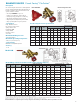
MODEL
NUMBER
VALVE SIZE
FIXED END
CONNECTION
FIXED END
DIMENSIONS
*
IN INCHES (mm) FLOW CAPACITY IN GPM (L/HR) APPROX.
WEIGHT
lbs. (kg)A B C D E F L MAX** G MAX** T MAX** MIN. MAX.
AM-1/2 1/2"
Sweat Female
1.7
(42)
5.8
(147)
3.8
(97)
2.4
(61)
1.2
(30)
6.7
(169)
7.6
(193)
8.2
(208)
1.55
(39)
0.18
(40)
4.84
(1,100)
2.5
(1.1)
NPT Female
1.7
(42)
5.8
(147)
3.8
(97)
2.4
(61)
1.2
(30)
–
(–)
7.6
(193)
–
(–)
1.55
(39)
0.18
(40)
4.84
(1,100)
2.5
(1.1)
AM-3/4 3/4"
Sweat Female
2.1
(53)
5.9
(150)
3.8
(97)
2.4
(61)
1.2
(30)
7.5
(191)
8.1
(205)
9.1
(231)
1.55
(39)
0.31
(70)
8.15
(1,850)
2.7
(1.2)
NPT Female
2.1
(53)
5.9
(150)
3.8
(97)
2.4
(61)
1.2
(30)
–
(–)
8.1
(205)
–
(–)
1.55
(39)
0.31
(70)
8.15
(1,850)
2.7
(1.2)
AM-1 1"
Sweat Female
2.5
(63)
6.1
(155)
4.1
(104)
2.4
(61)
1.2
(30)
8.3
(211)
9.1
(232)
10.3
(262)
2.00
(51)
0.44
(100)
10.35
(2,350)
3.3
(1.5)
NPT Female
2.5
(63)
6.1
(155)
4.1
(104)
2.4
(61)
1.2
(30)
–
(–)
9.1
(232)
–
(–)
2.00
(51)
0.44
(100)
10.35
(2,350)
3.3
(1.5)
AM-1-1/4 1 1/4"
Sweat Female
3.1
(79)
7.4
(188)
4.5
(114)
2.4
(61)
1.2
(30)
10.2
(259)
11.0
(279)
12.2
(310)
2.00
(51)
0.88
(200)
21.13
(4,800)
5.7
(2.6)
NPT Female
3.1
(79)
7.4
(188)
4.5
(114)
2.4
(61)
1.2
(30)
–
(–)
11.0
(279)
–
(–)
2.00
(51)
0.88
(200)
21.13
(4,800)
5.7
(2.6)
AM-1-1/2 1 1/2"
Sweat Female
3.4
(87)
8.1
(206)
4.7
(119)
2.4
(61)
1.2
(30)
11.7
(298)
12.9
(328)
14.3
(363)
2.52
(64)
1.76
(400)
32.76
(7,500)
7.9
(3.6)
NPT Female
3.4
(87)
8.1
(206)
4.7
(119)
2.4
(61)
1.2
(30)
–
(–)
12.9
(328)
–
(–)
2.52
(64)
1.76
(400)
32.76
(7,500)
7.9
(3.6)
AM-2 2"
Sweat Female
4.4
(112)
8.6
(218)
5.0
(127)
2.4
(61)
1.2
(30)
13.7
(347)
15.1
(384)
16.8
(427)
3.14
(80)
2.20
(500)
45.46
(10,300)
11.9
(5.4)
NPT Female
4.4
(112)
8.6
(218)
5.0
(127)
2.4
(61)
1.2
(30)
–
(–)
15.1
(384)
–
(–)
3.14
(80)
2.20
(500)
45.46
(10,300)
11.9
(5.4)
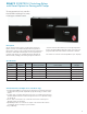
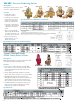
Model AM Specifications (
includes isolation valve and union tailpiece)
Circuit Sentry
Flo-Setter Specifications
Model AM
A
B
C
D
E
Circuit Sentry
Flo-Setter
Description
The Circuit Sentry Flo-Setter valve is a field adjustable
pressure independent flow limiter that maintains set
flow rates regardless of pressure fluctuations in the
system; eliminates overflow.
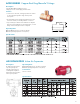
•
The unique GPM dial is easy to set.
Requires no instruments, charts or wheels
• Saves pump energy and improves coil efficiency
• No minimum straight pipe lengths required
• Integrated pressure / temperature ports included
• Large open flow paths for clog-free operation
Construction
Body: DZR Brass C35330
DP Controller: PPS 40% Glass
Spring: Stainless Steel
Diaphragm: HNBR
O-Rings: EPDM
Ball: Brass C37000
Seat: Teflon
Maximum Working Pressure
300 PSIG (2068 kPa)
Maximum Operating Temperature
-14°F (-10°C) to 230°F (110°C)
Control Range
Maximum 60 PSI (414 kPa) Delta P
Accuracy
+/ - 5%
New GPM dial
NOTE: Model AM valves are configured using the coil hook up confirgurator and include tail pieces and ball valves, therefore no part number is associated.