
Install Instructions

3
WARNING: WATER LEAKAGE HAZARD
To prevent leakage, make certain that the flange bolts
or ring nuts have been adequately tightened and that the
solder connections do not leak. Failure to follow these
instructions could result in serious personal injury, death
and/or property damage.
Apply torque in even increments to both flange bolts until a
value of 115 in-lbs. is reached. Both the suction and discharge
flange bolts must be torqued in this manner.
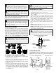
MODE OF DISCHARGE
The Model NRF/NBF Circulator can be installed to discharge
up or down, horizontally, left or right, but the motor shaft must
remain in the horizontal position, the arrow on the body must
point in the direction of the flow, the conduit box must be posi-
tioned on the top or to the side of the motor housing (see fig-
ure 2). If the conduit box position must be changed, it is best
to do so before installation. However, if the pump is already
installed, see the section titled “REMOVAL OF PUMP FROM
EXISTING SYSTEM FOR REPLACEMENT” before proceeding.
TO CHANGE THE CONDUIT POSITION
1. Remove the four (4)
1
/4-20 Allen screws (
3
/16 wrench) while
supporting the motor assembly.
2. Remove the motor assembly from the pump body and
rotate it to the desired position (see figure 2).
3. Replace the Allen screws and tighten evenly in a diagonal
method to 60 in-lbs.
4. Check to see that the impeller turns freely. Insert your finger
in the discharge port of the pump body (the arrow on the
pump body points in the direction of the discharge) until
you can feel the impeller and rotate it with your fingertip. If
the impeller does not turn easily, repeat the disassembly/
reassembly process.
WIRING INSTRUCTIONS
A. Loosen the screw securing the conduit box cover (wiring
compartment), and remove the screw & cover.
B. Attach the appropriate size connector to the hole in the side
of the conduit box.
C.Using a minimum size of 14 AWG copper electrical wire
(refer to your local code for wiring restrictions), wire the
motor to a single phase power source that matches the
electrical rating on the pump nameplate. See Fig. 3. Use
the size of electrical wire as dictated by local code.
D. Connect the ground wire to the inside of the conduit box
with one of the green screws provided inside the box. See
Fig. 4.
NOTE: Electrical supply and grounding wires must be suit-
able for at least 90°C (194°F).
NOTE: Model NRF/NBF Circulators are thermally protected
by impedance or on-winding thermal protectors and do not
require external overload protection.
SPEED SELECTION
The NRF/NBF can be run at different speeds to suit the
required operating conditions. The speed can be selected by
adjusting the 3 position switch on the side of the terminal box
(Fig. 4).
WARNING: HOT WATER HAZARD
When disassembling a gasketed joint, always use a
new gasket upon reassembly. NEVER RE-USE OLD
GASKETS. Failure to follow these instructions could result
in serious personal injury, death and/or property damage.
WARNING: HOT WATER HAZARD
Make sure that each flange gasket remains seated in
the flange groove during and after installation. Failure to
follow these instructions could result in serious personal
injury, death and/or property damage.
CAUTION: Make sure the power is turned off before
placing anything inside the discharge opening to
move the impeller. Failure to follow these instructions could
result in serious personal injury, death and/or property
damage.
FIG. 2
WARNING: ELECTRICAL SHOCK HAZARD
Disconnect and lock out the power before making
electrical connections. Failure to follow these instructions
could result in serious personal injury or death.
WARNING: ELECTRICAL SHOCK HAZARD
Be certain that all connections are secure and the
conduit box cover is closed before electrical power is
connected. Failure to follow these instructions could result
in serious personal injury, death and/or property damage.
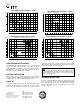
S
PUMP
MOTOR
LN
PUMP MOTOR
THERMALLY
PROTECTED
FUSIBLE DISCONNECT
OR CIRCUIT BREAKER BY
OTHERS
TYPICAL WIRING INSTALLATION SCHEMATIC
1Ø POWER SOURCE
TO REMOTE
CONTROL
IF REQUIRED
FIG. 3
CONDUIT BOX WIRING DETAIL
PUMP SPEED CONTROL
LINE
LEAD
GREEN
GROUND
SCREW
ADJUST PUMP SPEED BY
ROTATING CONTROL KNOB
TO POSITION
1: MINIMUM SPEED
2: MEDIUM SPEED
3: MAXIMUM SPEED
FIG. 4