
Instruction Manual

TECHNOFORCE Installation, Operation, and Maintenance
41
Operation
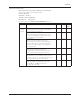
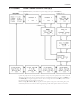
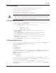
Press the NEXT/ ( ) key. The display now shows the following if any of the FLOW or PRESSURE
transmitters have been set up:
< >
Flow = $$
Pressure = $$
STAT1 STAT2 STAT3
Press the NEXT/ ( ) key. The display now returns back to the TechnoForce Pump Controller screen.
Note:
When system is showing any of the above screens and if any key is not pressed for “Delay to Display status”
time, then the fourth line will start showing the system status.
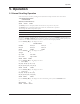
5.2 Types Of Programs
There are two operational programs with the TechnoForce family of controls. Refer to the nameplate on the
front of the controller to determine which program has been furnished.
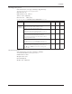
No. Of Program Description
CO Two Pumps/Two VFDs
Two 100% duty pumps and VFDs without staging.
DO Up to 6 Pumps/VFDs
All pumps may stage and run variable speed.
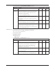
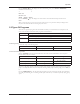
5.2.0 CO operation
Conrm the setup of the following items:
Section Item Value
4.10.1 Total # of pumps 2
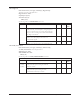
5.2.1 Local automatic operation
With the JUMPER connected on Terminal 200 and +24V check that the LED indicators on the Operator
Interface Panel (OIP) are as follows:
LED Condition Meaning
Start/Stop Off System is stopped.
No pumps running.
Pump 1 On/Off Flashing Green Pump1 is enabled but not on.
Pump 2 On/Off Flashing Green Pump2 is enabled but not on.
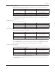
Take note of the pump sequence. Only the rst pump in the sequence will run in normal operation. The second
pump is a standby and will run only if the duty fails. To change which pump is the duty pump press the ALT/4
key.
Press the START/STOP key. The Off LED will turn solid green. After a brief delay the duty pump LED will
turn solid green indicating that it is running variable speed. It will then try to maintain setpoint by varying pump
speed.
▲ ▲