
Instruction Manual


TECHNOFORCE Installation, Operation, and Maintenance
33
Installation
Input the VFD number using the desired numeric keys for which the VFD Communication test needs to be
performed and then press the ENTER key. The following screen gets displayed:
VFD # (Same as Pump number)
Write: #####
Read: #####
Press Clear To Exit
If the controller is communicating properly with the VFD selected, both numbers will continue increasing in
value.
4.10.39 Alarm/events set up
Paths: Status Screens / Set up(3)
Press the LOG/5 key at the Main Set Up menu display. Then press the ENTER key.
The rst screen of Alarm/Events menu gets displayed:
< Selection: # 0=Exit >
1=Pump Failure
2=Low System
3=High System
Press the NEXT/( ) key to go to the next screen. The display now shows:
< Selection: # 0=Exit >
4=Low Suction
5=High Suction
6=NFSD
Press the NEXT/( ) key to go to the next screen. The display now shows:
< Selection: # 0=Exit >
7=Low Level
8=High Level
9=VFD/Comm
Pressing the NEXT/( ) key again will take the screen back to the rst screen.
Use the appropriate numeric key to select the setup menu desired, then press the ENTER key. A detailed
description of each menu follows. For example, to select the Pump Failure menu, press the PV/1 key and then
press the ENTER key.
4.10.40 Pump failure
Paths: Status Screens / Set up(3) / AlrmEvt(5) / Pump Failure(1)
The Pump Failure menu is displayed below:
Pump Failure
DP Proof Time: ##s
OK? $ (Y/N)
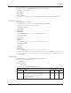
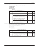
See following table for all PUMP FAILURE menu items.
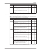
Pump Failure Menu Items
Menu Item Variable Default Range Field
Value
Pump DP Proof Time: ###s 10 0-999
Failure Proof timer prior to setting a pump fail alarm
after receiving a continuous high signal from a
DP switch, in seconds.
A value of 0 will disable this alarm.
▲
▲ ▲