
Instruction Manual


TECHNOFORCE Installation, Operation, and Maintenance
32
Installation
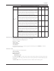
4.10.34 LED test
Paths: Status Screens / Set up(3) / Test(4) / LED(5)
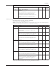
The LED test screen is displayed below:
LED Test
*** SOLID ***
*** OFF ***
*** FLASHING ***
All of the LED’s on the keypad will turn on, off, and then ash. The current status will be displayed on the
screen. The LED test is self terminating.
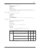
4.10.35 Key test
Paths: Status Screens / Set up(3) / Test(4) / Key(6)
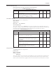
The KEY test screen is displayed below:
Key Test
Press a key to test
Press clear to exit
Press any key except for the CLEAR key, and the display will conrm that the key is working by displaying the
key name. Press CLEAR key to exit.
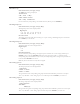
4.10.36 Display test
Paths: Status Screens / Set up(3) / Test(4) / Display(7)
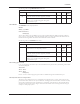
The DISPLAY test screen is shown below:
Press Clear To Exit
< 1 2 3 4 5 6 7 8 9
< 1 2 3 4 5 6 7 8 9
< 1 2 3 4 5 6 7 8 9
The display will show all black characters. Press CLEAR key to exit the test.
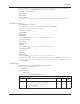
4.10.37 Communication test
Paths: Status Screens / Set up(3) / Test(4) / Comm(8)
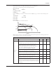
The COMMUNICATION test screen is shown below:
Communication Test
Read: ####
Write: ####
Press Clear to Exit
If the controller is communicating properly with the building automation system, both numbers will continue
increasing in value. For Modbus protocol, the read and write numbers should be equal and increasing with every
poll. For BACnet, both numbers should be increasing, but they will not be equal. The write value will increase
even when not connected.
For the JC Metasys N2 protocol, both numbers should be increasing but may not be equal. If both numbers are
not increasing in value, the controller is not communicating properly. Check the wiring at the terminal blocks. See
section 4.10.18 for more information on communications setup. Press CLEAR to exit this test.
4.10.38 VFD comm
Paths: Status Screens / Set up(3) / Test(4) / VFD Comm(9)
The VFDCOMMUNICATION test screen is shown below:
VFD Comm Test
VFD Number: # (Same as Pump number)
Press Clear To Exit