
Instruction Manual


TECHNOFORCE Installation, Operation, and Maintenance
27
Installation
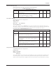
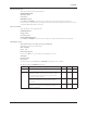
See following table for all JC METASYS N2 menu items.
JC Metasys N2 Menu Items
Menu Item Variable Default Range Field
Value
JC Metasys Node: ### 10 0-255
N2 The node number should be supplied by the BMS.
AI Ovrd = $ N Y/N
Select “Y” to override analog inputs through the
communications port.
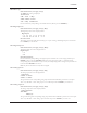
4.10.21 Modbus
The MODBUS screen is displayed below:
Modbus
9600, 8, 1, 1, N RTU
Node: # Al Ovrd: $
OK: $(Y/N)
The rst line conrms setup for Modbus protocol. The second line denes the 9600 bps baud rate, 8 bit data
pack, 1 stop bit, 1 start bits, and no parity. The third line requires user input. Obtain the node number from the
manufacturer that supplied the device that will communicate with the Controller.
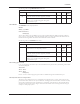
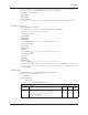
See following table for all MODBUS menu items.
Modbus Menu Items
Menu Item Variable Default Range Field
Value
Modbus Baud: ##### 9600 9600,
The baud rate is user adjustable parameter 19200,
38400
Node: ### 10 0-255
The node number should be supplied by the BMS
communications port.
AI Ovrd: $ N Y/N
Select “Y” to override analog inputs through the
communications port.
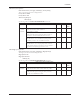
4.10.22 Analog Input Override
If “Y” was entered for “AI Ovrd” in any of the communication setup screens above, the following screen will be
automatically displayed:
AI Override
AI1: $ AI2: $
AI3: $ AI4: $
OK $(Y/N)
Enter a “Y” next to each analog input type that will be overridden through the communications port.
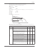
4.10.23 Dynamic Flow Loss Compensation:
This energy savings feature allows user to compensate for the friction losses of system. As ow increases, the
pressure losses due to friction in the system will increase accordingly. This feature will allow controller to modify
the setpoint in real time based on the speed changes to compensate system friction loss. The controller will log
the last 40 real time setpoint changes. Figure 1 shows how this function works with setup parameters using an
example of a three pump system.