
Instruction Manual

TECHNOFORCE Installation, Operation, and Maintenance
18
Installation
9 = I/O SETUP
10 =COMMUNICATIONS
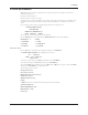
Press the NEXT/( ) key to go to the next screen. The display now shows:
< SELECTION: # >
11 = SPECIAL FUNCTIONS
12 = SAVE/LOAD
13 = DISPLAY 0 = EXIT
Pressing the NEXT/( ) key again will take the screen back to the rst screen.
Use the appropriate numeric key to select the desired menu, then press the ENTER key. A detailed description
of each menu follows. For example, to select the STAGE/DESTAGE menu, press the PV/1 key and then press
the ENTER key.
4.10.3 Stage/ destage menu
Paths: Status Screens / Set up(3) / System(3) / StageDestage(1)
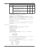
The rst screen has been displayed below:
< SELECTION: # >
1 = PV STAGE 0=EXIT
2 = PV DESTAGE
3 = EOC STAGE
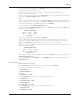
Press the NEXT/( ) key to go to the next screen.
The display now shows:
< SELECTION: # >
4=EOC DESTAGE 0=EXIT
5=FLOW DESTAGE
6=POWER LIMIT STAGE
By pressing the appropriate numeric key and ENTER key, the setup can be completed.
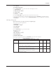
See the following table for all STAGE/DESTAGE menu items.
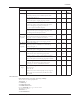
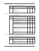
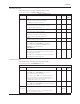
STAGE/DESTAGE SETUP MENU ITEMS
Menu Item Variable Default Range Field
Value
PV Stage Stg Spd: ##% 95 0-100
The maximum speed at which the lead pump will
operate prior to starting a lag pump, %.
Stg Proof Timer: ### s 30 0-999
Proof timer prior to starting lag pump, seconds.
Stab Timer: ###s 60 0-999
Staging stabilization time, delay prior to calculating
destage value, seconds.
▲
▲
▲