
Instruction Manual
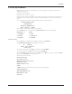

TECHNOFORCE Installation, Operation, and Maintenance
15
Installation
4.10 Set up & features
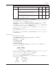
Note: Many sections of the Set up & Features show a path for navigation. An example is shown below to
understand the given path.
Example for system setup path.
Path: Status Screen / Setup(3) / System(3)
To follow the above path press the SETUP/3 key from the system status screen. Then press the SETUP/3 key
for number 3 which is a selection number for system and press ENTER key. It will lead to the system setup
screen.
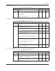
Upon powering up the controller, the display will light and show the following screen:
<TECHNOFORCE PUMP>
CONTROLLER
MM/DD/YY HH:MM:SS A/P
STOP MANUAL NORM
The current date and time will be displayed on the third line.
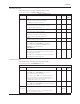
Press the SETUP/3 key once and the following MAIN SET UP menu items will be displayed:
SELECTION: # 0=EXIT
1 = SENSORS 4 = TEST
2 = PUMPS 5 = ALRM/EVT
3 = SYSTEM 6 = Q-START
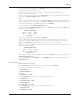
4.10.0 Sensor Setup
Press the PV/1 key at the Main Set Up menu display. Then press the ENTER key.
The SENSOR SET UP MENU will be displayed as shown below:
AI 1 TYPE: $$$
SPAN= ### ZERO= ##
< OK $ (Y/N) >
To accept the current values, press YES/7 key and then press the ENTER key.
To set up each eld, press the NO/0 key and then press the ENTER key.
The current TYPE eld starts blinking. Press the up (▲) and down (▼) keys to navigate to the desired TYPE
and then press the ENTER key to conrm selection.
The following selections are valid:
SYS (System Pressure)
SUC (Suction Pressure)
RESYS (Redundant System Pressure)
FLOW (System Flow)
PRESS (For Monitor only)
NONE
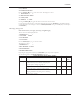
If RESYS is selected as a desired eld, the following screen will get displayed:
ACTIVE SENSOR ##
DRIFT THRESHOLD ##%
DRIFT PR TM ###s
OK $ (Y/N)