
Instruction Manual

TECHNOFORCE Installation, Operation, and Maintenance
10
Differential pressure switches are installed to sense the increase in pressure between the pump suction and
discharge gauge taps and are used to determine whether a pump is running. Each switch should be wired from
the normally closed contact.
To control variable frequency drives it is necessary to wire RS485 with each VFD.
With certain bypass and control methods it is necessary to disable the adjustable frequency drive from running.
This is accomplished by wiring from the terminals to each VFD’s interlock terminals. Should this wiring be
required, any jumpers which may be found on the VFD’s interlock terminals should be removed.
The control family may be provided with the capability to accept many analog inputs. Typically all analog inputs
must be 4-20mA and powered by the 24VDC power supply in the controller. All shields must be grounded in the
controller only to prevent ground loops and improper signals.
Hardwire communications refers to the capability of the Controller to communicate with an energy management
system. Standard communication features are listed below:
Remote Start/Stop – Remove the jumper from Terminal 200 and install a switch as indicated on the wiring
diagram. CLOSED CONTACT of this switch will provide the start signal.
Remote Alarm Indication – A digital output rated 2.5 AMPs at 240V is supplied. This output closes to indicate
an alarm condition exists.
User Congurable I/O – The Controller comes equipped with the capability to dene the operation of any
unused input or output signal. Refer to System Set Up I/O menus.
4.4 Pump package location guidelines
WARNING:
• Assembled units and their components are heavy. Failure to properly lift and support this equipment can
result in serious physical injury and/or equipment damage. Lift equipment only at the specically identied
lifting points. Lifting devices such as eyebolts, slings, and spreaders must be rated, selected, and used for the
entire load being lifted.
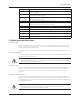
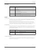
Guideline Explanation
Make sure that the space around the pump This facilitates ventilation, inspection,
package is sufcient. maintenance, and service.
If you require lifting equipment such as hoist or This makes it easier to properly use the lifting
tackle, make sure that there is enough space above equipment and safely remove and relocate the
the pump package. components to a safe location.
Protect the unit from weather and water damage This is applicable if nothing else is specied.
due to rain, ooding, and freezing temperatures.
Do not install and operate the equipment in closed Acceptable devices:
systems unless the system is constructed with • Pressure relief valves
properly-sized safety devices and control devices. • Compression tanks
• Pressure controls
• Temperature controls
• Flow controls
If the system does not include these devices,
consult the engineer or architect in charge before
you operate the pump.
Take into consideration the occurrence of The best pump location for noise and vibration
unwanted noise and vibration. absorption is on a concrete oor with subsoil
underneath.
Installation