INSTALLATION, OPERATION AND MAINTENANCE INSTRUCTIONS 10-001-265 REV 5 TECHNOFORCE Pump Controller VARIABLE SPEED PUMPING SYSTEMS
TECHNOFORCE Installation, Operation, and Maintenance
Table of Contents Table of Contents 1. Introduction and safety.....................................................................................................................................................1 1.1 Introduction.....................................................................................................................................................................1 1.2 Safety.........................................................................................................
Table of Contents 4.10.22 Analog Input Override.............................................................................................................................. 27 4.10.23 Dynamic Flow Loss Compensation........................................................................................................ 27 4.10.24 Save/Load.................................................................................................................................................... 29 4.10.
Table of Contents 6.13 Troubleshooting........................................................................................................................................................ 49 6.14 Program Type and Version Number..................................................................................................................... 50 6.14.0 Log Menu..................................................................................................................................................
TECHNOFORCE Installation, Operation, and Maintenance
Introduction and Safety 1. Introduction and Safety 1.1 Introduction 1.1.0 Purpose of the manual The purpose of this manual is to provide necessary information for: • Installation • Operation • Maintenance CAUTION: Read this manual carefully before installing and using the product. Improper use of the product can cause personal injury and damage to property, and may void the warranty. NOTICE: Save this manual for future reference, and keep it readily available at the location of the unit.
Introduction and Safety 1.3.1 Hazard levels Hazard level Indication DANGER: A hazardous situation which, if not avoided, will result in death or serious injury. WARNING: A hazardous situation which, if not avoided, could result in death or serious injury. CAUTION: A hazardous situation which, if not avoided, could result in minor or moderate injury. NOTICE: • A potential situation which, if not avoided, could result in undesirable conditions.
Introduction and Safety 1.6 User safety 1.6.0 General safety rules These safety rules apply: • Always keep the work area clean. • Pay attention to the risks presented by gas and vapors in the work area. • Avoid all electrical dangers. Pay attention to the risks of electric shock or arc flash hazards. • Always bear in mind the risk of drowning, electrical accidents, and burn injuries. 1.6.1 Safety equipment Use safety equipment according to the company regulations.
Introduction and Safety 1.6.4 Wash the skin and eyes Do the following if chemicals or hazardous fluids have come into contact with your eyes or your skin: If you need to wash your . . . Then . . . Eyes 1. Hold your eyelids apart forcibly with your fingers. 2. Rinse the eyes with eyewash or running water for at least 15 minutes. 3. Seek medical attention. Skin 1. Remove contaminated clothing. 2. Wash the skin with soap and water for at least one minute. 3.
Transportation and Storage 2. Transportation and Storage 2.1 Inspect the delivery 2.1.0 Inspect the package 1. Inspect the package for damaged or missing items upon delivery. 2. Note any damaged or missing items on the receipt and freight bill. 3. File a claim with the shipping company if anything is out of order. If the product has been picked up at a distributor, make a claim directly to the distributor. 2.1.1 Inspect the unit 1. Remove packing materials from the product.
Product Description 3. Product Description 3.1 General description 3.1.0 Description The controller is a specific purpose programmable pump controller. This provides: • Optimum pump control without the cost of general purpose control hardware. • Software dedicated and established for the unit. • Unique analog input protection of other members of the control family. In the event of a short circuit condition, the current limit circuitry prevents failure of the analog input components.
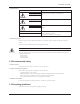
Product Description Nameplate Data Explanation Model Number The manufacturer’s number to indicate the particular type of product which has been acquired. Serial Number A set of characters that uniquely identifies a single unit and can be used for traceability and warranty purposes. Station Voltage The rated voltage at which the station has been designed for. Should match the application site supply voltage.
Product Description 3.4.4 Analog signals Shielded cable (#22 AWG, Belden type 8762, Alpha #2411, or equal) should be installed for all D.C. control wiring. The shield must be terminated in the Controller panel. Do not connect the shield at the other end of the cable! Insulate the shield so that no electrical connection is made at the other end of the cable. A twisted pair of #22 AWG conductors (Belden 8442, or equal) can be used in place of shielded cable.
Installation 4. Installation 4.1 Field connections 4.1.0 Diagrams Review the wiring diagrams and dimensional drawings before you install and operate the unit. 4.1.1 Electrical precautions WARNING: • Prevent electrical shocks. Disconnect the power supply before beginning installation. FAILURE TO FOLLOW THESE INSTRUCTIONS COULD RESULT IN SERIOUS PERSONAL INJURY, DEATH AND/OR PROPERTY DAMAGE. • Each motor must have a properly sized drive. Ground fault protection should be sized properly.
Installation Differential pressure switches are installed to sense the increase in pressure between the pump suction and discharge gauge taps and are used to determine whether a pump is running. Each switch should be wired from the normally closed contact. To control variable frequency drives it is necessary to wire RS485 with each VFD. With certain bypass and control methods it is necessary to disable the adjustable frequency drive from running.
Installation 4.5 System piping and unit installation – final checklist 1. Check that the unit base is properly leveled, grouted and secured. 2. Check that all lubrication points are properly lubricated per motor manufacturer’s instructions. 3. Check that the shut-off valves to the transmitters open. 4. Check that the shut-off valves to the pump suction open. 5. Check that the shut-off valves to the discharge line open. 6. Check that the piping is properly supported to prevent strains on the unit. 7.
Installation 4.7 Operator interface panel 4.7.0 Diagrams The OIP consists of a 4 x 20 character LCD screen and a 26 button keypad with LEDs which display system status. 4.7.1 Key functionality The names of the keys on the Operator Interface Panel (OIP) are shown as CAPITAL LETTERS in this manual. Table 1 shows the functionality of the keys on the OIP.
Installation 4.7.2 Table 1 Key Functionality Key Name START/STOP Functionality Starts or stops the system. AUTO/ MANUAL Toggles the operation mode. The system must be stopped to change the operation mode. PUMP 1-6 ENABLE Enables or disables the corresponding pump. Pumps cannot be disabled while they are failed. RESET/ SILENCE This key is used to reset alarms and events. When the A/V Alarm relay output is set. Pressing of this key resets the alarms and events.
Installation 4.8 LEDs Table 2 gives the meaning of the LED states. LED Description START/STOP On = Start Off = Stop AUTO/ MANUAL On = Auto Off = Manual PUMP 1-6 On = Pump On Off = Pump Disabled Blink = Pump Ready, Blink Fast = Pump Failed RESET/ SILENCE Off = OK Blink = Reset Required HELP Off = OK Blink = Event/Alarm(press HELP from the status screens to view) 4.9 I/O 4.9.
Installation 4.10 Set up & features Note: Many sections of the Set up & Features show a path for navigation. An example is shown below to understand the given path. Example for system setup path. Path: Status Screen / Setup(3) / System(3) To follow the above path press the SETUP/3 key from the system status screen. Then press the SETUP/3 key for number 3 which is a selection number for system and press ENTER key. It will lead to the system setup screen.
Installation RESYS MENU ITEMS Menu Item Variable Default Range Field Value RESYS Active Sensor : ## 1 1-4 5 0-100 Enter the active system pressure sensor number Drift Threshold: ##% Pressure difference limit between the active and redundant pressure sensor in % Drift Pr Tm : ##s Proof timer prior to give warning when exceed the drift threshold limit, in seconds 0 0-999 To set up each field, press the NO/0 key and then press the ENTER key.
Installation To set up each field, press the NO/0 key and ENTER key. Modify the values as desired using the appropriate keys. Modify the values as desired for pump 1. Note: For example, to enter a value of 3.5 Amps, go to the amps field, press numerical key 3 and press enter. Then press key 5 and enter. ▲ To change the values for other pumps, press the NEXT/( ) key. This is only applicable if the total numbers of pumps selected in TOTAL PUMPS: # field are more than 1.
Installation 9 = I/O SETUP 10 =COMMUNICATIONS < ) key to go to the next screen. The display now shows: ▲ Press the NEXT/( SELECTION: # > 11 = SPECIAL FUNCTIONS 12 = SAVE/LOAD 13 = DISPLAY 0 = EXIT ) key again will take the screen back to the first screen. ▲ Pressing the NEXT/( Use the appropriate numeric key to select the desired menu, then press the ENTER key. A detailed description of each menu follows.
Installation STAGE/DESTAGE SETUP MENU ITEMS (continued) Menu Item Variable Default Range Field Value PV Destage Destage: ###% 85 0-100 Enter the percentage of the stabilized speed at which the lag pump will stop, %. Destg Pr Timer: ### s Proof timer prior to stopping lag pump, seconds. HD Spd: ### % The lowest speed at which parallel pumps will operate prior to destaging the lag pump, %. It must be greater or equal to minimum frequency.
Installation Use the appropriate numeric key to select the desired menu, then press the ENTER key. See the following table for all VFD menu items.
Installation Note: 1. Use the (▲) and (▼) keys to select the appropriate resolution values ) key to select the desired sign(+ or -) for VALUE and OFFSET ▲ ) key and Prev/( ▲ 2. Use the Next/( variables 4.10.5 Exercise menu Paths: Status Screens / Set up(3) / System(3) / Exercise(3) See the following table for all EXERCISE menu items.
Installation 4.10.9 Daily alternation The Daily Alternation screen is displayed below: Daily Alt. Time: HH:MM Enable: $ (Y/N) OK? $(Y/N) To edit the alternation time, press the NO/0 key and ENTER key. Modify the values as desired. Enter the Alternation Time in 24Hr format (range being 0:00-23:59) at which pumps will alternate daily. Press YES/7 key to enable Daily alternation. Press the YES/7 key again to confirm the selection. 4.10.
Installation 4.10.12 Alternation basis See the following table for ALTERNATION BASIS menu items. Alternation Basis Menu Items Menu Item Variable Default Range Field Value Alternation Basis 1=Pump Sequence 1 1-2 (The next pump in sequence will become the lead pump after alternation) 2=Pump Run Time (The pump with the lowest run time will become the lead pump after alternation) 4.10.
Installation 4.10.15 Date, time menu Paths: Status Screens / Set up(3) / System(3) / Date, Time(7) See the following table for all DATE, TIME menu items Date, time Menu Items Menu Item Variable Default Range Field Value Date/Time MM Enter the current month using both digits, example Jan. should be entered as 01. DD Enter the current date using both digits, example the 6th should be entered as 06. YYYY Enter the current year using all 4 digits.
Installation Password Menu Items (continued) Menu Item Variable Default Range Field Value Verify VERIFY THE PASSWORD PASSWD >_ _ _ _ _ _< After entering data in password definition screen this screen requires the user to confirm the requested password. If the confirmed number does not agree with the first number the Enter New Password screen is repeated to allow the user to get both input screens to agree. 4.10.
Installation 4.10.18 Communication menu Paths: Status Screens / Set up(3) / System(3) / Communication(10) See the following table for all COMMUNICATION menu items. Communication Menu Items Menu Item Variable Default Range Field Value SELECTION SELECTION: # 0 1-3 Select the software protocol to drive the communications on the optional RS-485 port. 1 = BACnet, 2 = JC Metasys, 3 = MODBUS, 0 = EXIT 4.10.
Installation See following table for all JC METASYS N2 menu items. JC Metasys N2 Menu Items Menu Item Variable Default Range Field Value JC Metasys N2 Node: ### The node number should be supplied by the BMS. 10 0-255 AI Ovrd = $ N Y/N Select “Y” to override analog inputs through the communications port. 4.10.21 Modbus The MODBUS screen is displayed below: Modbus 9600, 8, 1, 1, N RTU Node: # Al Ovrd: $ OK: $(Y/N) The first line confirms setup for Modbus protocol.
Installation Paths: Status Screens / Set up(3) / System(4) / Frict. Loss Comp. (11) The Friction Loss Compensation screen has been displayed below: Frict. Loss: ### Auto: $ > Enable: $ Log Stab Tmr: ###S Log Reset: $ OK? $ Press the YES/7 key to confirm the selection or Press next (►) key to go to the next screen. The display now shows:
Installation Friction Loss Compensation Menu Items (Continued) Menu Item Variable Default Range Field Value Loss2 : ### The max loss in PSI that will be compensated for two pumps. This value will be used to adjust the setpoint when two pumps are running. This value will get subtracted from the setpoint as a fixed value when less than two pumps are running. Loss3 : ### The max loss in PSI that will be compensated for three pumps. Frict. Loss Comp.
Installation 4.10.26 Load from flash The Load From Flash screen is displayed below: LOAD FROM FLASH All Settings will be Overwritten! PROCEED: $ (Y/N) Press YES/7 and ENTER to overwrite all of the current user setup information with the data that was previously saved to the flash memory. Loading from flash memory will load all setup information that was saved to the Flash PROM chip within the controller. 4.
Installation 4.10.29 Test set up Paths: Status Screens / Set up(3) / Test(4) The TEST menu screen gets displayed: Test Selection: # 1=DI 4=AO 2=DO 5=LED 3=AI 6=Key 7=Disp 8=Comm 9=VFD Comm Press the numeric key corresponding to the desired sub-menu, and then press the ENTER key. 4.10.
Installation 4.10.34 LED test Paths: Status Screens / Set up(3) / Test(4) / LED(5) The LED test screen is displayed below: LED Test *** SOLID *** *** OFF *** *** FLASHING *** All of the LED’s on the keypad will turn on, off, and then flash. The current status will be displayed on the screen. The LED test is self terminating. 4.10.
Installation Input the VFD number using the desired numeric keys for which the VFD Communication test needs to be performed and then press the ENTER key. The following screen gets displayed: VFD # (Same as Pump number) Write: ##### Read: ##### Press Clear To Exit If the controller is communicating properly with the VFD selected, both numbers will continue increasing in value. 4.10.39 Alarm/events set up Paths: Status Screens / Set up(3) Press the LOG/5 key at the Main Set Up menu display.
Installation 4.10.41 Low system pressure Paths: Status Screens / Set up(3) / AlrmEvt(5) / Low System(2) The Low System Pressure menu is displayed below: Low Sys Press: ##PSI Low Sys Pr Tm: ##s Alarm: $ Stop Pumps: $ OK? $ (Y/N) See following table for all LOW SYSTEM PRESSURE menu items.
Installation 4.10.43 Low suction pressure Paths: Status Screens / Set up(3) / AlrmEvt(5) / Low Suction(4) The Low Suction Pressure menu is displayed below: Low Suct. Press: ## Pr Tm: ##s Alarm: $ Auto Rst: $ Source: $$(AI/DI) Reset PSI: ## OK: $ (Y/N) See following table for all LOW SUCTION PRESSURE menu items.
Installation 4.10.44 High suction pressure Paths: Status Screens / Set up(3) / AlrmEvt(5) / High Suction(5) The High Suction Pressure menu is displayed below: High Suct. Press: ## High Suct Pr Tm: ##s Alarm: $ Alarm: $ Source: $$(AI/DI) Reset Press: ## OK: $ (Y/N) See following table for all HIGH SUCTION PRESSURE menu items.
See following table for all NO FLOW SHUT DOWN menu items. No Flow Shut Down Menu Items Menu Item Variable Default Range Field Value No Flow Shut Down NFSD Tst Pr. Tmr: #s 10 0-999 The No Flow Shut Down test proof timer is the amount of time, in seconds, the controller will run the system while the PV is greater then SP. A value of 0 will disable this alarm. Min Spd Pr.
4.10.47 High level Paths: Status Screens / Set up(3) / AlrmEvt(5) / High Level(8) The High Level menu is displayed below: High Level Time: ###s Stop Pumps?: $(Y/N) Auto Reset?: $(Y/N) OK? $ (Y/N) See following table for all HIGH LEVEL menu items. High level Menu Items Menu Item Variable Default Range Field Value High Level High Level Time: ###s 0 0-999 The proof time, in seconds prior to setting a high level event, see section 4.10.
Installation 4.11 Q-Start Paths: Status Screens / Set up(3) Press the QuickAccess/6 key at the Main Set Up menu display. Then press the ENTER key. ▲ ▲ Q-Start will prompt the user for the parameters required to start up the system quickly. Some of these values will already be correct due to the factory setup that is done for each TechnoForce Pump Controller. Use PREV/( ) and NEXT/( ) to navigate through these screens.
Operation 5. Operation 5.1 Normal Scrolling Operation Other screens may be viewed by scrolling from the TechnoForce Pump Controller screen shown below: CONTROLLER MM/DD/YY HH:MM:SS A/P STAT1 STAT2 STAT3 The STAT1 portion of the display indicates the current start/stop status of the system. The STAT2 portion of the display indicates the current auto/manual mode of operation.
Operation ▲ Press the NEXT/ ( ) key. The display now shows the following if any of the FLOW or PRESSURE transmitters have been set up: < > Flow = $$ Pressure = $$ STAT1 STAT2 ) key. The display now returns back to the TechnoForce Pump Controller screen. ▲ Press the NEXT/ ( STAT3 Note: When system is showing any of the above screens and if any key is not pressed for “Delay to Display status” time, then the fourth line will start showing the system status. 5.
Operation 5.2.2 Remote automatic operation With the Remote start/stop contact is connected on Terminal 200 and +24V, check that the LED indicators on the Operator Interface Panel (OIP) are as follows: LED Condition Start/Stop Off Meaning System is stopped. No pumps running. Pump 1 On/Off Flashing Green Pump1 is enabled but not on. Pump 2 On/Off Flashing Green Pump2 is enabled but not on.
Operation 5.3 Pump Rotation 1. It will be necessary to operate all pumps in variable speed to check for proper rotation. 2. Place the TechnoForce into operation as described in previous sections. 3. Run each pump in auto noting rotation in each. 4. If rotation is wrong, exchange the wiring on two motor phases. NOTE: Changing phase at VFD input does not change output phasing. DANGER: • High voltage 3 phase power can kill. Pumps can start automatically.
Operation To select the SCHEDULE SET POINT menu, press the SET PT/2 key and then press the ENTER key. The following menu will be displayed: Set Point 1> Mon – Fri HH:MM - ## Start Time 1 - Set Point 1 HH:MM - ## Start Time 2 - Set Point 2 Exit: $ ▲ Two different set point values can be scheduled for Set Point 1 from Monday to Friday and similarly for Saturday and Sunday. Press the NEXT/( ) key to schedule the set point values for Saturday and Sunday.
Operation To view possible causes for alarm/event, press the HELP key again after the alarm/event is displayed. Refer to table below for an overview of the possible alarm/event and their respective causes. Press the CLEAR key to return to the main screen. After addressing the source of the alarm/event, press RESET to re-start the system and/or clear the alarm/event. The controller logs alarm/event as they occur to aid in troubleshooting unobserved alarm/event. Refer to Section 6.14.
Maintenance 6. Maintenance 6.1 Preface The following is a description of the hardware, diagnostics, and corrective action to maintain a process being controlled by the Pump Controller. NOTE: THE FOLLOWING SHOULD NOT BE INTERPRETED AS THE MAXIMUM CONFIGURATION OF THIS CONTROLLER, RATHER THIS DESCRIBES ITS APPLICATION AS A TECHNOFORCE PUMP CONTROLLER ONLY. 6.
Maintenance 6.8 Power Supply The power supply provides 24 VDC for all digital and analog signals as well as the CPU. It is specifically rated only for the controller and other loads should not be applied without factory approval. The power supply is protected with both primary and secondary fusing as indicated on the wiring diagram. The size of these fuses is indicated on a sticker inside each enclosure. DANGER: • Troubleshooting live control panels exposes personnel to hazardous voltages.
Maintenance 6.11 Field Repair 6.11.0 General Typical field repair should include: replacing fuses, replacing input/output modules and assuring connections are correct and secure. DANGER: • Troubleshooting live control panels exposes personnel to hazardous voltages. Electrical troubleshooting must only be done by a qualified electrician. FAILURE TO FOLLOW THESE INSTRUCTIONS COULD RESULT IN SERIOUS PERSONAL INJURY, DEATH, AND/OR PROPERTY DAMAGE. 6.
Maintenance 6.13 Troubleshooting VFD FAILURE a. Remedy: i. Cycle Power to VFD and Station. ii. Check power wiring and fuses for affected VFD. iii. Check all wiring between VFD and PLC. iv. Check to be sure VFD is not in LOC mode. HIGH LEVEL: a. Remedy: i. Check application for legitimate ‘high level’ fault. ii. Check that PLC is properly programmed for the correct number of switches/sensors. iii. Check for open or closed switch contacts. Refer to wire diagrams for proper connection. HIGH SUCTION: a.
Maintenance 6.14 Program type and version number To check the program type and version number, press the INFO/8 key while at the Pump Controller status screen. The screen will now display: Sys Info CPU V ### AS V ### OS #### Prog Type: ##### Scheme No: # SW# ## Press the CLEAR key to exit this screen. The # symbol will be replaced by the actual version numbers and program type. If the factory is called for information or service on this unit this information may be requested. 6.14.
Maintenance 6.14.3 Pump log Paths: Status Screens / Log(5) / Pump Log (2) / Pump Log(1) The display now shows: MMDD HHMM PUMP ON/OFF MESSAGE MMDD HHMM PUMP ON/OFF MESSAGE MMDD HHMM PUMP ON/OFF MESSAGE MMDD HHMM PUMP ON/OFF MESSAGE ▲ ▲ Every pump ON/OFF occurrence will be logged along with the date and time. The forty most recent occurrences will be stored. The date is displayed in MMDD format and the time is displayed in HHMM format. The most recent occurrence is shown first.
Maintenance 6.14.8 Totalized value Paths: Status Screens / Log(5) / Data Log(3) / Totalized Value(2) The display now shows: Total KWHr ### Total Flow ###KGal The total accumulated kilowatt hours and Flow is displayed as the Totalized Value 6.14.9 Operation Paths: Status Screens / Log(5) / Operation(4) The display now shows: 1=Op Mode Changes 2=Power Cycles 3=Events ) key to go to the next screen.
Maintenance 6.14.12 Events Paths: Status Screens / Log(5) / Operation(4) / Events(3) The display now shows: Selection: # 0=Exit 1=System On/Off 2=Alternation 3= Sys Rset 4=Events Use the appropriate numeric key to select the desired sub-menu, then press the ENTER key. A detailed description of each sub-menu appears. 6.14.
Maintenance 6.14.16 Events Paths: Status Screens / Log(5) / Operation(4) / Events(3) / Events(4) The display now shows: MMDD HHMM Event Message MMDD HHMM Event Message MMDD HHMM Event Message MMDD HHMM Event Message ▲ ▲ Every time an event occurs, it gets logged. The forty most recent logs will be stored. The date is displayed in MMDD format and the time in 24 hour HHMM format. The most recent event will be shown first. Press NEXT/( ) and PREV/( ) to view more log events. Press CLEAR to exit. 6.
Maintenance 6.14.20 Service log Paths: Status Screens / Log(5) / Service Log(5) The display now shows: 1 = Error Log 2 = Operation Hours 3 = Destage Speed 4 = Run Time Setpoint ) key to see the next display. The display now shows: ▲ Press the NEXT ( Use the appropriate numeric key to select the desired sub-menu, then press the ENTER key. A detailed description of each sub-menu appears. 6.14.
Maintenance 6.15 Maintenance (Physical) 6.15.0 Electrical No maintenance is required for the electrical panel except to keep the modules free of dirt and dust that might hold moisture. Cabinet door should be kept closed, and the components kept dry. 6.15.1 Mechanical • If a B&G pump was supplied it was lubricated at the factory. Future lubrication should be according to the instructions that came with the pump. • If there is a danger of freezing, drain the pump. Inspect pump and system piping regularly.
Appendix 7. Appendix 7.
Appendix 7.2 Conformance Statement BACnet Protocol Implementation Conformance Statement Date: 10/19/2010 Vendor Name: Xylem Product Name: TechnoForce Pump Controller Product Model Number: N/A Applications Software Version: 1.16 or above Firmware Revision: N/A BACnet Protocol Revision: 4.0 Product Description The TechnoForce Pump Controller is a variable speed pumping system for water booster systems.
Appendix Analog output Dynamically creatable: No Dynamically deletable: No Optional properties supported: None Writable properties: Present Value Proprietary properties: None Property range restrictions: None Dynamically creatable: No Dynamically deletable: No Optional properties supported: None Writable properties: Present Value Analog value Conditionally writable Out Of Service Proprietary properties: None Out Of Service Property range restrictions: None Dynamically creatable: N
Appendix Device Dynamically creatable: No Dynamically deletable: No Optional properties supported: Local_Date Local_Time Max_Master Max_Info_Frames Writable properties: Max_Master Proprietary properties: None Property range restrictions: None Data Link Layer Options ❑ BACnet IP, (Annex J) ❑ BACnet IP, (Annex J), Foreign Device ❑ ISO 8802-3, Ethernet (Clause 7) ❑ ANSI/ATA 878.1, 2.5 Mb. ARCNET (Clause 8) ❑ ANSI/ATA 878.
Appendix 7.3 TechnoForce BACnet Communication Objects List for Application Version 1.16 or Above Object Identifier Object Name Binary Input, 1 P1 Failure Binary Input, 2 Binary Input, 3 Range 1 = Failure 0 = O.K. P1 VFD Failure 1 = Failure 0 = O.K. P1 Off 1 = Alarm 0 = O.K. Binary Input, 4 P2 Failure 1 = Failure 0 = O.K. Binary Input, 5 P2 VFD Failure 1 = Failure 0 = O.K. Binary Input, 6 P2 Off 1 = Alarm 0 = O.K. Binary Input, 7 P3 Failure 1 = Failure 0 = O.K.
Appendix Object Identifier 62 Object Name Range Analog Input, 1 System Pressure 0 to Span (in TechnoForce User Setup Menu) Analog Input, 2 Suction Pressure 0 to Span (in TechnoForce User Setup Menu) Analog Input, 3 AI #1 0 to Span (in TechnoForce User Setup Menu) Analog Input, 4 AI #2 0 to Span (in TechnoForce User Setup Menu) Analog Input, 5 AI #3 0 to Span (in TechnoForce User Setup Menu) Analog Input, 6 AI #4 0 to Span (in TechnoForce User Setup Menu) Analog Input, 7 Setpoint #1 0
Appendix 7.4 TechnoForce MODBUS Communication Points Function Points # Point Code Description Range/ Value Modbus Address 02 1 Pump #1 Failure 1 = Failure 0 = O.K. 10001 02 2 Pump #1 VFD Failure 1 = Failure 0 = O.K. 10002 02 3 Pump #1 Off Alarm 1 = Alarm 0 = O.K. 10003 02 4 Pump #2 Failure 1 = Failure 0 = O.K. 10004 02 5 Pump #2 VFD Failure 1 = Failure 0 = O.K. 10005 02 6 Pump #2 Off Alarm 1 = Alarm 0 = O.K. 10006 02 7 Pump #3 Failure 1 = Failure 0 = O.K.
Appendix TechnoForce MODBUS Communication Points (continued) Function Points # Point Code Description 64 Range/ Value Modbus Address Units 04 1 System Pressure 0 to Span (in TechnoForce 30001 User Setup Menu) PSI 04 2 Suction Pressure 0 to Span (in TechnoForce User Setup Menu) 30002 PSI 04, 06 3 AI #1 0 to Span (in TechnoForce User Setup Menu) 30003, 40003 04, 06 4 AI #2 0 to Span (in TechnoForce User Setup Menu) 30004, 40004 04, 06 5 AI #3 0
Appendix Function Points # Point Code Description 04 25 Speed % Range/ Value Modbus Address 0 to 100 30025 Units % 04 26 Lead Pump Number 1 to Pump # (in TechnoForce User Setup Menu) 30026 04 27 Active Zone Number 1 to Zone # (in TechnoForce User Setup Menu) 30027 7.5 TechnoForce Metasys N2 Comunication Points NPT NPA Point Description Range/Value BI 1 Pump #1 Failure 1 = Failure 0 = O.K. BI 2 Pump #1 VFD Failure 1 = Failure 0 = O.K.
Appendix NPT 66 NPA Point Description BI 35 Analog Input #3 Failure BI 36 BI 37 Range/Value 1 = Failure 0 = O.K. Analog Input #4 Failure 1 = Failure 0 = O.K. General Alarm 1 = Alarm 0 = O.K.
Appendix 7.
Appendix 7.
Appendix 8. Symbols # - Numeric input field, such as 0, 1, 2,...
Xylem 1) The tissue in plants that brings water upward from the roots; 2) a leading global water technology company. We’re 12,500 people unified in a common purpose: creating innovative solutions to meet our world’s water needs. Developing new technologies that will improve the way water is used, conserved, and re-used in the future is central to our work. We move, treat, analyze, and return water to the environment, and we help people use water efficiently, in their homes, buildings, factories and farms.