OmniView® Secure KVM Switch Belkin Tech Support US: 800-282-2355 310-898-1100, ext. 2263 UK: 0845 607 77 87 Australia: 1800 235 546 New Zealand: 0800 235 546 Singapore: 65 64857620 Europe: www.belkin.com/support Belkin International, Inc. Belkin International, Inc. 501 West Walnut Street Los Angeles, CA 90220, USA 310-898-1100 310-898-1111 fax Belkin Ltd. 4 Pioneer Avenue Tuggerah Business Park Tuggerah, NSW 2259, Australia +61 (0) 2 4350 4600 +61 (0) 2 4350 4700 fax Belkin B.V.
OmniView® Secure KVM Switch User Manual F1DN102U F1DN104U F1DN108U
Table of Contents 1. Introduction ............................................................................................. 1 Package Contents .......................................................................... 1 2. Overview ................................................................................................. 2 Security Features ........................................................................... 2 Other Features ................................................................
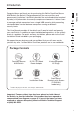
Introduction This User Manual provides all the details you’ll need to install and operate your new Switch, in addition to expert troubleshooting advice—in the unlikely event of a problem. For quick and easy installation, please refer to the Quick Installation Guide included in your packaging. We appreciate your business and are confident that you will soon see for yourself why over 1 million Belkin OmniView products are in use worldwide.
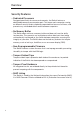
Overview Security Features • Dedicated Processors Designed specifically for secure environments, the Switch features a dedicated processor per computer port. This keeps each computer running on different security levels completely separated and secure at all times, and prevents any unintended data transfer between computers. • No Memory Buffer The Switch does not have a memory buffer and does not have the ability to store data.
Overview 1 • USB Support 2 The Switch is compatible with USB 1.1 and USB 2.0 technology and supports Plug-and-Play connectivity with USB computers, keyboards, and mice. • Video Resolution The Switch supports video resolutions of up to 1920x1440@75Hz. • Dedicated Port Selectors Port selectors, located conveniently on the front panel of the Switch, allow you to switch easily from one computer to the next. Each button controls a single computer port.
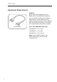
Overview Equipment Requirements Cables Belkin highly recommends you use Belkin All-In-One USB KVM Cable Kits for your Switch to help ensure superior performance. These cables offer the highest quality possible to ensure optimal data and video transmission. One Cable Kit is required per connected computer. F3X1962bXX All-In-One USB KVM Cable Kits: F3X1962b06 – 6 ft. (1.8m) F3X1962b10 – 10 ft. (3m) F3X1962b15 – 15 ft. (4.6m) Note: Due to USB limitations, the USB-cable length cannot exceed 15 feet (4.6m).
Overview System Requirements The Switch is compatible with computers running on, but not limited to, the following OS platforms: • Windows® 2000 • Windows XP (Home/Professional) • Windows 2003 Server • Windows Vista® • Red Hat® Linux® Desktop • Red Hat Enterprise Linux WS 2 3 4 5 • Mac OS® X v10.
Overview Unit Display Diagrams Front View LED Indicators �� �� �� �� Port Selectors Back View Console USB Keyboard Port Console USB Mouse Port Console VGA Monitor Port Computer VGA & USB Ports DC Power Jack Side View Tamper-Evident Tape (F1DN104U model shown) IMPORTANT NOTICE: There should be one tamper-evident tape on each side of the Switch enclosure (total of two tapes).
Overview 1 Specifications F1DN102U, F1DN104U, F1DN108U Enclosure: Metal enclosure with high-impact plastic faceplate 2 Power Requirements: 5V DC, 2.5A (minimum) power adapter with center-pin-positive polarity4 3 AC Input: 100 to 240VAC Interchangeable AC Plugs: 4 (U.S., U.K., Europe, Australia) 4 No. of Users Supported: 1 No.
Installation Pre-Configuration Where to place the Switch: The enclosure of the Switch is designed for desktop or rack-mount configuration. The 8-Port Switch (F1DN108U) can be mounted to a standard 19-inch server rack using the included rack-mount brackets and screws. An optional Rack-Mount Kit (Belkin part number F1D005) is available for use with the 2- and 4-Port Switches.
Installation Step 1 Mounting the Switch (optional) Bracket Installation (F1DN108U) 1.1 1.2 Determine how far you would like the Switch to protrude from the rack. Select a bracket-hole scheme. Attach the bracket to the side of the Switch using the Phillips screws provided. (Refer to diagram below.) 2 3 4 5 6 7 1.3. Mount the Switch to the rack rails. (Refer to diagram below.) Your Switch is now mounted securely to the rack and you are ready to connect your console.
Installation Bracket Installation (F1DN102U and F1DN104U) The 2- and 4-Port Switches can be installed into a 19-inch rack using an optional Rack-Mount Kit, sold separately (Belkin part number F1D005). 1.1 Attach the Rack-Mount Bracket to the Switch using the Phillips screws provided. (Refer to diagram below.) 1.2 Mount the Switch to the rack rails. (Refer to diagram below.) Your Switch is now mounted securely to the rack and you are ready to connect your console.
Installation 1 Warning: Before attempting to connect anything to the Switch or your computers, please ensure that all computer equipment and devices are powered off. Plugging and unplugging cables while computers are powered on may cause irreversible damage to the computers and/or the Switch. Belkin International, Inc., is not responsible for damage caused by your failure to do so.
Installation Step 3 Connecting Computers to the Switch (required) 3.1 Make sure all computers and the Switch are powered off. 3.2 Using the Belkin All-In-One USB KVM Cable Kit (F3X1962bXX), connect the male VGA connector to the monitor port on your computer. Then connect the female VGA connector to the CPU monitor port on the Switch labeled “VGA 01”. (Refer to diagram below.) 3.3 Using the Cable Kit, connect the USB Type A connector to an available USB port on your computer.
Installation Step 4 Powering Up the Systems (required) 1 4.1 2 3 4 5 6 4.2 7 Power on your computers and your monitor. All computers can be powered on simultaneously. Note: Your computers should recognize the Switch and automatically install the HID USB driver if necessary. When you power on your computers, the Switch emulates both a mouse and keyboard on each port and allows your computers to boot normally. The computer connected to port “1” will be displayed on the monitor.
Using your Switch Selecting a Computer Using Port Selectors Now that you have connected your console and computers to the Switch, it is ready for use. You can select which computer you wish to control by pressing the corresponding port selector on the front of the Switch. The LED will illuminate to indicate which computer (or port) is currently selected. It takes approximately 1–2 seconds for the video signal to refresh after switching computers.
Frequently Asked Questions What does NIAP Common Criteria validation to EAL 4 mean? To learn more about NIAP Common Criteria and EAL 4, visit http://niap.nist.gov/cc-scheme/nstissp-faqs.html. What do I do if I find that the tamper-evident tape on the Switch has been removed or disrupted? How does the Switch allow the user to switch between computers? The Switch only supports one method of port selection. The user can access the desired computer by pushing the port selectors.
Troubleshooting General Problem: My computer does not boot when connected to the Switch but works fine when I connect my keyboard, video, and mouse directly to my computer. Solution: • Make sure that the All-In-One USB KVM Cable Kit is connected tightly between the Switch and the computer. Video Problem: I am getting ghosting, shadowing, or fuzzy images on my monitor. Solution: • Check that all video cables are inserted properly to the Switch, computer, and monitor.
Troubleshooting Keyboard Problem: The computer does not detect my keyboard, or my keyboard does not work when I switch computers or reboot. Solution: • Check that the keyboard you are using is connected properly to the Switch. • Check that the USB cable between the Switch and the computer is completely connected. • Try connecting to a different USB port on the computer. • If you are using keyboard software that was included with your keyboard, uninstall it and then reinstall.
Troubleshooting Mouse Problem: The computer does not detect my mouse, or my mouse does not work when I switch computers or reboot. Solution: • Check that the mouse you are using is connected properly to the Switch. • Check that the USB cable between the Switch and the computer is completely connected. • Try connecting to a different USB port on the computer. • Make sure the mouse works when directly plugged into the computer (the HID USB driver is installed on the computer).
Information FCC Statement Declaration of Conformity with FCC Rules for Electromagnetic Compatibility We, Belkin International, Inc., of 501 West Walnut Street, Compton, CA 90220, declare under our sole responsibility that the products: F1DN102U, F1DN104U, F1DN108U, to which this declaration relates: Comply with Part 15 of the FCC Rules.
Information How to get service. To get service for your Belkin product you must take the following steps: 1. Contact Belkin International, Inc., at 501 W. Walnut St., Compton CA 90220, Attn: Customer Service, or call (800)-223-5546, within 15 days of the Occurrence. Be prepared to provide the following information: a. The part number of the Belkin product. b. Where you purchased the product. c. When you purchased the product. d. Copy of original receipt. 2.
Information 1 2 3 4 5 6 21 section 7