
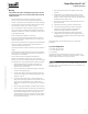
Install Instructions

6
10/20 - Subject to change. © Belimo Aircontrols (USA), Inc.
71161-00001.F
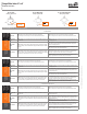
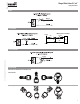
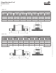
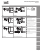
ANSI 125
Flange Detail for American Standard 125 lb. Cast Iron Pipe Flanges
FLANGES DRILLING BOLTING
Nominal
Pipe Size
A
Flange
Diameter
B
Flange
Thickness
C
Diameter of
Bolt Circle
D
Diameter of
Bolt Holes
Number
of Bolts
Diameter
of Bolts
E
Length of
Machine Bolts
2½” 7” ¹¹⁄₁₆” 5½” ¾” 4 ⁵⁄₈” 2½”
3” 7½” ¾” 6” ¾” 4 ⁵⁄₈” 2½”
4” 9” ¹⁵⁄₁₆” 7½” ¾” 8 ⁵⁄₈” 3”
5” 10” ¹⁵⁄₁₆” 8½” ⁷⁄₈” 8 ¾” 3”
6” 11” 1” 9½” ⁷⁄₈” 8 ¾” 3¼”
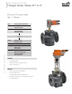
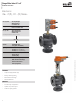
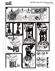
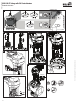
Flanged Globe Valves 2½” to 6”
Installation Instructions
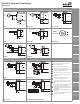
ANSI 250
Flange Detail for American Standard 250 lb. Cast Iron Pipe Flanges
FLANGES DRILLING BOLTING
Nominal
Pipe Size
A
Flange
Diameter
B
Flange
Thickness
F
Diameter of
Raised Face
C
Diameter of
Bolt Circle
D
Diameter of
Bolt Holes
Number
of Bolts
Diameter
of Bolts
E
Length of
Machine Bolts
2½” 7½” 1” 4 ¹⁵⁄₁₆” 5 ⁷⁄₈” ⁷⁄₈” 8 ¾” 3¼”
3” 8¼” 1¹⁄₈” 5 ¹¹⁄₁₆” 6 ⁵⁄₈” ⁷⁄₈” 8 ¾” 3¼”
4” 10” 1¼” 6 ¹⁵⁄₁₆” 7 ⁷⁄₈” ⁷⁄₈” 8 ¾” 3¾”
5” 11” 1 ³⁄₈” 8 ⁵⁄₁₆” 9 ¼” ⁷⁄₈” 8 ¾” 4”
6” 12½” 1⁷⁄₁₆” 9 ¹¹⁄₁₆” 10 ⁵⁄₈” ⁷⁄₈” 12 ¾” 4”