
Install Instructions

2
G
2…
,
G
3… NPT Threaded
G
lobe
C
ontrol Valve
s
Instruct
io
n Manua
l
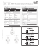
Mounting
Pre
f
erred Mountin
g
O
ptional Mountin
g
D
O
N
O
T IN
S
TALL WITH A
C
TUAT
O
R BEL
O
W PIP
E
A
llow 6" for actuator/adaptor bracket removal. N
O
TE: D
O
N
O
T
CO
VER ADAPT
O
R
BRA
C
KET WITH IN
SU
LATI
O
N MATERIAL
.
6”
Installation
1
. Inspect shippin
g
packa
g
e, valve, linka
g
e, and actuator
f
or physical
damage. If shipping damage has occurred notify appropriate carrier. Do
n
ot install.
2
. I
f
a replacement, remove existing valve, linkage and actuator
f
rom the
pi
p
i
ng system.
3
. If actuator and linka
g
e are removed, they must be reinstalled correctly.
T
he actuator must be rotated so that the valve sits
p
ro
p
erl
y
for close off.
4
. Install valve with the
p
ro
p
er
p
orts as inlets and outlets. Check that inlet
a
nd outlet of 2-wa
y
valves are correct; check that the "A","B", and "AB"
p
orts of 3-way valves are piped correctly for mixing or diverting. See
supplied drawings on previous page
.
5. Blow out all pipin
g
and thorou
g
hly clean before valve installation.
6
.
C
lean male pipe threads with wire brush and rag. If threads have been
d
amage
d
or expose
d
to weat
h
er, runn
i
ng a tap or
di
e over t
h
e t
h
rea
d
s
m
ay straighten them.
C
lean pipes, threads, and valve threads before
i
nstallation; check
f
or any
f
oreign material that can become lodged in trim
c
omponents.
S
trainers should be cleaned after initial startup
.
7. Pipe sealing compound should be applied sparingly after cleaning and
m
a
y
not be a
pp
lied to the two lead threads of a screwed
p
i
p
e, which are
i
nnermost inside the valve. Sealing compound is to be placed on male
th
rea
d
s on
l
y.
Th
e purpose
i
s to
l
u
b
r
i
cate t
h
e p
i
pes w
h
en t
i
g
h
ten
i
ng
.
8.
V
alve must be installed per the mountin
g
drawin
g
s shown
.
9
.
S
tart the connection by turning the valve or pipe by hand as far as
p
ossible. Be certain the threads mate by the "feel" of the connection.
10
.
U
se wrenc
h
es to t
i
g
h
ten t
h
e va
l
ve to t
h
e p
i
pe.
D
o not over t
i
g
h
ten or str
i
p
th
e t
h
rea
d
s.
T
wo wrenc
h
es are necessary to avo
id
d
amag
i
ng t
h
e va
l
ve.
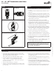
1
1.
T
wo-way valve Normally Open or Closed confi gurations must be verifi ed
b
y exam
i
n
i
ng
b
ot
h
t
h
e mec
h
an
i
ca
l
d
raw
i
ngs an
d
t
h
e va
l
ve an
d
actuator.
See
de
t
a
il
s
be
l
o
w.
12
.
T
hree-way valve Normally
O
pen or
C
losed confi
g
urations for the
C
ontrol
Port and the Bypass Port must be verifi ed by examinin
g
both the
m
echanical drawin
g
s and the valve and actuator.
In the pipin
g
dia
g
rams the A and B ports may need to be reversed or the
a
ctuator set up sprin
g
open or fail safe open differently than shown.
The s
p
ecifi c a
pp
lication determines what fail safe mode is re
q
uired for
freeze or moisture control if applicable.
•
A
void installations where valve ma
y
be ex
p
osed to excessive moisture,
corrosive fumes, vibration, hi
g
h ambient temperatures, elements, or hi
g
h
traffi c areas with potential for mechanical dama
g
e
.
•
Valve assembly location must be within ambient ratin
g
s o
f
actuator.
•
Th
e va
l
ve assem
bl
y w
ill
requ
i
re
h
eat s
hi
e
ldi
ng, t
h
erma
l
i
so
l
at
i
on, or
cooling i
f
combined e
ff
ect o
f
medium and ambient temperatures
–
conduction, convection, and radiation – is above 122°F
f
or prolonged
t
i
me per
i
o
d
s at t
h
e actuator.
•
S
trainers should be installed before coil and valve
.
• Visual access must be
p
rovided. Assembl
y
must be accessible
f
or routine
scheduled service. Contractor should
p
rovide unions for removal from line
an
d
i
so
l
at
i
on va
l
ves.
•
A
void excessive stresses. Mechanical su
pp
ort must be
p
rovided where
r
educers have been used and the pipin
g
system may have less structural
i
nte
g
rity than full pipe sizes.
•
S
uffi cient upstream and downstream pipin
g
runs must be provided to
ensure proper valve capacity and
fl
ow response. Five diameters in each
di
rect
i
on are recommen
d
e
d
.
•
Li
f
e span o
f
valve stems and packing is dependent on maintaining
n
on-damaging conditions. Poor water treatment or
fi
ltration, corrosion,
sca
l
e, ot
h
er part
i
cu
l
ate can resu
l
t
i
n
d
amage to tr
i
m components.
A
water
t
reatment spec
i
a
li
st s
h
ou
ld
b
e consu
l
te
d.
•
N
orma
l
t
h
rea
d
engagement
b
etween ma
l
e p
i
pe t
h
rea
d
an
d
va
l
ve
b
o
d
y
should be observed. Pipe run that is in too
f
ar will damage the valve.
Warning!
Valve should not be used for combustible
g
as applications. Gas leaks and explosions may result. Do not install in systems which exceed the
r
atin
g
s of the valve
.
1
0/17 - Sub
j
ect to chan
g
e. © Belimo Aircontrols
(
USA
)
, Inc
.
72009-00001.
B