
User Guide

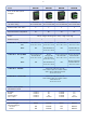


Rateofowandtotalowmaybeshownoneitherthe6or
8 digit displays. If only one variable is required, the lower
six digit display may be disabled.
8 DIGITS
Total flow display
6 DIGIT
Rate of flow display
Alarm status annunciators
Flow symbol ‘rotates’ when
pulse input frequency exceeds 2Hz
Total and rate displays
may be reversed
Lower display may be
disabled
Fig 6 Rate Totaliser display
Thetotaldisplaymayberesettozerobyoperatingtwoofthe
Rate Totaliser’s push buttons, or remotely by connecting
the instruments external reset terminals together for more
than one second.
The Rate Totaliser also maintains a protected Grand Total
whichisnotresetwhenthetotaldisplayiszeroed.Both
the total display and the grand total are retained when the
Rate Totaliser is not powered.
4. Rate Totaliser Conguration
Allmodelsareconguredandcalibratedusingacommon
intuitive menu structured in the same way as all BEKA
instruments. The menu is accessed via the four instrument
pushbuttonsandcanbeprotectedbyauserdenedfour
digit access code. The calibration structure of all single
input Rate Totalisers is shown in Fig 7. This allows a Rate
Totaliser to be congured and calibrated on-site without
the need for external test equipment.
The conguration menu uses English language names
to describe functions and variables such as code and
debounce. When the function name has more than eight
characters a simple abbreviation is used such as di5p-1
(Display1)andt-re5et(Totalreset).InthisApplication
Guide these function and variable names are shown in a
seven segment font, exactly as they appear on the Rate
Totaliser’s display.
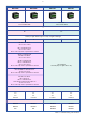
BEKA rate Totalisers are easy to calibrate as there are
only four basic variables to adjust.
Flowmeter K-factor factor
Total scale factor 5cale t
Rate scale factor 5cale r
Timebase t-ba5e
Therstthreevariables,factor, 5cale t and 5cale r divide
thenumberofinputpulsesfromtheowmetertoconvertthem
to meaningful engineering units, such as gallons or litres. As
showninFig7theyarearrangedsothatthetotalowand
therateofowcanbeshownindifferentengineeringunits.
Each variable is adjustable between 0.0001 and 99999 and
is described separately in the following sections.
Pulse input
÷
Flowmeter K factor FACtor
Dividing factor usually adjusted
to equal flowmeter K-factor.
Adjustable between
0.0001 and 99999
Note: When the 16
segment lineariser Lin is
selected in the Function menu
up to 16 values of FACtor
may be entered each starting
at a specified pulse frequency
÷
Rate scale factor 5CALE
.
r
Dividing factor to convert pulse
output from FACtor into the
required units for the rate display
Adjustable between
0.0001 and 99999
X
Timebase t-bA5E
÷
Total scale factor 5CALE
.
t
Dividing factor to convert pulse
output from FACtor into the
required units for the total display
Adjustable between
0.0001 and 99999
Total display
Grand Total 8 high & 8 low digits
1 for rate per second
60 for rate per minute
3,600 for rate per hour
Rate display
888888
88888888
88888888 88888888
Fig7SingleinputRateTotaliserCongurationstructure
4.1 Flowmeter K-factor
Each output pulse from a owmeter or ow transducer
representsadenedowvolumethathaspassedthrough
theowmeter.Formostowmetersthisissmallcompared
withthetotalowvolume thatis tobe measured. The
performance of owmeters and ow transducers is
therefore dened by the number of output pulses they
produceforeachunitofowvolumepassingthroughthem
e.g.200pulsespergallonofow.Thisisknownasthe
K-factorofthemeterortransducer.Mostowmetersand
transducersaresuppliedwithatestcerticateshowingthe
averageK-factoroverarangeofowrates.
To convert the pulse output from a owmeter or ow
transducer into engineering units, the number of output
pulsesmustbedividedbytheK-factoroftheowmeteror
owtransducer.
9