
User Guide


2.2.2 Explosive atmosphere applications
ToselectaRateTotaliserforahazardousareainstallation,
the Zone or Division in which it is to be installed and
the hazard must be known, together with the required
certicationauthorityi.e.IECEx,ATEXorETL.
The range includes intrinsically safe Ex ia models for
installation in most gas and dust Zones. For installations
in Zone 2 or 22 without the need for Zener barriers or
galvanic isolators, models with non-sparking Ex nA
certicationforgashazardsanddustignitionprotectionby
enclosure Ex tc are included.
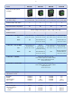
Field mounting see Table 1
BA334E 1 input 1G Ex ia Separate terminal
compartment.
BA334G 1 input 1GD Ex ia
BA384E 2 input 1G Ex ia Separate terminal
compartment.
BA384G 2 input 1GD Ex ia
BA334NG 1 input 3GD Ex nA and Ex tc
BA384NG 2 input 3GD Ex nA and Ex tc
Panel mounting see Table 2
BA337E 1 input 96 x 48mm 1G Ex ia
BA338E 1 input 144 x 72mm 1G Ex ia
BA337E-SS 1 input Rugged 105 x 60mm 1GD Ex ia
BA388E 2 input 144 x 72mm 1G Ex ia
BA337NE 1 input Rugged 105 x 60mm 3GD Ex nA
and Ex tc
When selecting a Rate Totaliser for installation in a
hazardousarea,theinstrument’shazardousareacerticate
should be consulted to ensure that the instrument has
approval for the required area, hazard and temperature
range.
2.3 Two input models
The two input Rate Totalisers are primarily intended for
use with two owmeters. Each Rate Totaliser input is
individually congurable and the instrument can display
eitherinput,orthesumordifferenceofthetwoowrates
and totals.
Thetwoinputmodelsenablethetotalowandowrate
from two sources to be calculated and displayed. If it
is required to add more than two ow sources, multiple
Rate Totalisers can be linked using the instrument’s
synchronous pulse output.
2.4 Operating temperature
All the eld and panel mounting Rate Totalisers except
modelswithan‘E-SS’,‘NG’and‘NE’sufxhaveaspecied
operating temperature of -40°C to +70°C. Between these
temperatures the Rate Totalisers will function normally,
however at temperatures below -20°C the display digits
will gradually change more slowly and contrast will be
reduced. At some temperature below -20° the display will
stop functioning, but totalisation will continue normally and
the instrument will not be damaged.
Modelswithan‘E-SS’,‘NG’and‘NE’sufxhaveamaximum
certicationtemperatureof+60°Cbutperformanceisthe
same as the other models at low temperatures.
3. Rate Totaliser function
All BEKA externally powered pulse input Rate Totalisers
have similar functions, although the number of inputs and
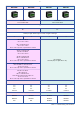
the output options may differ. Fig 5 shows a simplied
block diagram of a one input instrument.
All models can accept pulses from a wide variety of
owmeter transducers or outputs. To enable a Rate
Totaliser to count pulses from transducers such as a
switch contact, open collector transistor or a two wire
proximity detector, the transducer has to be powered
whichisachievedbyttinganexternallinkbetweentwoof
theRateTotaliser’seldterminals.
1
2
3
4
5
6
RS1
RS2
Power
supply
A4
A3
A2
A1
Alarm
2
Alarm
1
+
+
Optional
isolated
alarms
C4
C3
C2
C1
+
Optional
isolated
4/20mA
output
Optional
backlight
internally
powered
Processor
Display
+
+
+
Link to
energise
input
Input
Pulse low
Pulse high
Magnetic pick-off
Proximity detector
Switch contact
Open collector
Isolated pulse output is optional on 96x48mm panel mounting models
External
reset
P2
P1
+
Earth
Isolated
pulse
output
Fig5SimplieddiagramofsingleinputRateTotaliser
RateTotaliserscancalculateanddisplaytherateofow
and the total ow from most pulse output owmeters
including non-linear owmeters such as a turbine meter
operatingoverawiderangeofows.Allmodelsinclude
a sixteen segment lineariser which can be congured
to minimise non-linearity errors. Rate Totalisers with
two inputs have separate conguration functions and a
separate lineariser for each input.
All the Rate Totaliser models have separate rate and total
displays as shown in Fig 6 with independent calibration
allowingtherateofowandthetotalowtobedisplayed
indifferentunitsofmeasurement.e.g.rateofowcould
beshowninlitresperhourandthetotalowcouldbein
cubic metres. The display digit size depends upon the
model as shown below.
Display size
6 digits 8 digits
Field mounting
All models 12mm 18mm
Panel mounting
96 x 48mm 6mm 9mm
144 x 72mm 12mm 18mm
Rugged 105 x 60mm 6mm 9mm
8