
User Guide

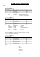

Modbus Register Address Map
Notes:
In the tables below (IEEE) indicates that data is represented by a 4 byte IEEE floating point format
For 32 bits registers (integers or floats), the Most Significant 16 bits word is the one with the highest Modbus address.
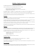
Coils
Read /
Write
Address Bits Description Functions Supported
1 1 Alarm1 Enable 1, 5, 15
2 1 Alarm2 Enable 1, 5, 15
3 1 4/20 O/P Enable 1, 5, 15
4 1 Save Configuration 1, 5, 15
Notes:
Enable: 0 = Disable 1= Enable
Save: 0 = No Effect 1 = Save Configuration Data in Flash
(Coil will revert to zero once saved)
Input Status
Read
Only
Address Bits Description Functions Supported
1 1 Alarm1 Energised 2
2 1 Alarm2 Energised 2
3 1 Input Fault Status 2
4 1 Configuration Not Saved 2
5 1 Alarm Option Fitted 2
6 1 4/20 O/P Option Fitted 2
7 1 Tare Display Status 2
8 1 Write Error 2
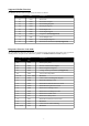
Notes:
Alarms: 0 = De-Energised 1= Energised
Fault Status: 0 = Normal 1 = Fault
Configuration: 0 = Saved 1 = Changed, but not saved
Options: 0 = Not Fitted 1 = Fitted
Tare Display: 0 = Gross 1 = Tare
Write: 0 = No Error 1 = Error *
* A value of 1 indicates that the last attempt to write to the unit generated an error due to the fact that one or
more of the data registers were outside the allowable range. It should be noted that any valid value within this
same request would have still been processed, i.e. the entire write packet is not rejected.
The flag is cleared at the start of a transaction.
Input Registers
Read
Only
Address Registers Description Functions Supported
1 1 Input Type 4
2 2 Display Value (IEEE) 4
4 2 Max Hold Value (IEEE) 4
6 2 Min Hold Value (IEEE) 4
8 2 Display Value (32 bits Integer) 4
10 1 Display Value divisor (n/10) 4
11 2 Max Hold (32 bits Integer) 4
13 1 Max Hold divisor (n/10) 4
14 2 Min Hold (32 bits Integer) 4
16 1 Min Hold divisor (n/10) 4
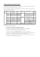
Notes:
Input Type Enumeration: 0 = 0.1V
1 = 1V
2 = 10V
3 = 4/20 mA
4 = 0-50 mA
5 = Differential RTD
6 = 2-Wire RTD
7 = 3-Wire RTD
The divisor register defines the number of times the integer value is divided by ten
9