
User Guide


Notes:
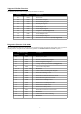
Input Unit Enumeration:
(Only for Temperature Inputs)
0 = Degrees Celsius
2 = Degrees Fahrenheit
4 = Resistance
1 = Degrees Kelvin
3 = Degrees Rankine
Function (Root extraction)
(Only for Current Inputs)
0 = No Root extraction 1 = Root extraction
Resolution
(of least significant digit)
0 = 1
2 = 5
1 = 2
3 = 10
D.P. (Decimal Point position on
the Display:)
0 = 00000 (No Decimal Point)
2 = 000.00
4 = 0.0000
1 = 0000.0
3 = 00.000
5 = Auto (gives best resolution)
Bar Type 0 = OFF
2 = Centre
4 = AlrSP (if alarms are fitted)
1 = Left
3 = Right
Alarm Hi/Lo 0 = Alarm is a Low Alarm 1 = Alarm is a High Alarm
Alarm ND/NE 0 = Alarm Normally De-Energised 1 = Alarm Normally Energised
Alarm Flash Enable 0 = Disables Alarm Flashing 1 = Enables Alarm Flashing
Alarm Latch Enable 0 = Disables Alarm Latching 1 = Enables Alarm Latching
ACSP Enable 0 = Disables Alarm Menu shortcut 1 = Enables Alarm Menu shortcut
Tare Enable 0 = Disables Tare function 1 = Enables Tare Function
Hold Enable 0 = Disables Hold function 1 = Enables Hold Function
Hold Clear 0 = No effect 1 = Clears max/min held values.
U – P (Function of P Button) 0 = % of Span 1 = Analogue Input
Serial Baud (Modbus baud rate) 0 = 9600
2 = 38400
4 = 115200
1 = 19200
3 = 57600
Serial Par (Modbus Parity) 0 = None
2 = Even
1 = Odd
Factory Default Colour Codes
(each colour assigned to a code
can be adjusted manually
through the menu)
1 = Red
2 = Orange
3 = Light Green
4 = Green
5 = Blue
6 = Purple
7 = White
4/20 O/P RTD Fault Current 0 = No Fault Current
1 = 3.6 mA
2 = 3.8 mA
3 = 21 mA
Calibration source 0 = Factory (SET) 1 = User (CAL)
float = IEEE Floating Point The entire 32 bits value has to be written and read as one command
rather than separately otherwise an ILLEGAL ADDRESS exception will
be raised
sigint = 32 bits Signed Integer with Divisor The divisor register defines the number of times the integer value is
divided by ten.
The divisor and 32 bits value have to be written and read together
otherwise an ILLEGAL ADDRESS exception will be raised.
For 32 bits registers (either integers or floats), the Most Significant 16 bits word is the one with the highest Modbus
address.
If the register written to does not apply to the option fitted or the input type, the write will be allowed but the underlying
value will not be changed and the write rejected flag will not be set. Read requests will return a value of 0. This
behaviour avoids generating exceptions which would prevent a full group write.
The ASCII Character set for access codes is limited by the characters that can be displayed on a 7 segment digit. The
following characters may be used:
0,1,2,3,4,5,6,7,8,9,A,B,C,D,E,F,G,H,I,J,L,N,O,P,R,T,U,V,Y
11