
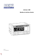
User Guide


Holding
Registers
Read /
Write
Address Registers Description Default Range Exceptions
Functions
Supported
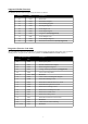
1 2 Set Zero (IEEE) 0.0 float Only applicable to Voltage & Current Inputs 3, 16
3 2 Set Span (IEEE) 100.0 float Only applicable to Voltage & Current Inputs 3, 16
5 2 Bar Low (IEEE) * float 3, 16
7 2 Bar High (IEEE)
* float
3, 16
9 2 Alarm1 Setpoint (IEEE)
0.0 float Only applicable if Option fitted
3, 16
11 2 Alarm1 Hysteresis (IEEE)
0.0 float
3, 16
13 2 Alarm2 Setpoint (IEEE)
0.0 float
3, 16
15 2 Alarm2 Hysteresis (IEEE)
0.0 float
3, 16
17 2 4/20 O/P Zero (IEEE)
* float
3, 16
19 2 4/20 O/P Span (IEEE)
* float
3, 16
21 1 Input Units
0 0…4 Only applicable to RTD Inputs
3, 6,16
22 1 Function (Root Extraction)
0 0…1 Only applicable to Current Inputs
3, 6,16
23 1 Resolution (of least significant digit)
0 0…3
3, 6,16
24 1 D.P. (Decimal Point position on the display)
* 0…5
3, 6,16
25 1 Bar Type
1 0…4
3, 6,16
26 1 Alarm1 Hi/Lo
0 0…1 Only applicable if Option fitted
Not all characters are available. See Note.
3, 6,16
27 1 Alarm1 ND/NE
0 0…1
3, 6,16
28 1 Alarm1 Delay (in seconds)
0 0…3600
3, 6,16
29 1 Alarm1 Silence
0 0…3600
3, 6,16
30 1 Alarm1 Colour (Colour Preset Number)
1 1…7
3, 6,16
31 1 Alamr1 Flash Enable
1 0…1
3, 6,16
32 1 Alarm1 Latch Enable
0 0…1
3, 6,16
33 1 Alarm2 Hi/Lo
0 0…1
3, 6,16
34 1 Alarm2 ND/NE
0 0…1
3, 6,16
35 1 Alarm2 Delay (in seconds)
0 0…3600
3, 6,16
36 1 Alarm2 Silence
0 0…3600
3, 6,16
37 1 Alarm2 Colour (Colour Preset Number)
1 1…7
3, 6,16
38 1 Alarm2 Flash Enable
1 0…1
3, 6,16
39 1 Alarm2 Latch Enable
0 0…1
3, 6,16
40 2 Alarms Access Code
“0000” ASCII
3,16
42 1 ACSP Enable
0 0…1
3, 6,16
43 1 Tare Enable
0 0…1
3, 6,16
44 1 Hold Enable
0 0…1
3, 6,16
45 1 Hold clear
0 0…1
3, 6,16
46 1 U – P (Function of P Button)
0 0…1
3, 6,16
47 1 Serial Baud
1 0…4
3, 6,16
48 1 Serial Par
2 0…2
3, 6,16
49 1 Serial Stop
1 1…2
3, 6,16
50 1 Serial Addr
1 1…247
3, 6,16
51 1 4/20 O/P RTD Fault Current
0 0…3 Only applicable if Option fitted
3, 6,16
52 2 Security Code
“0000” ASCII Not all characters are available. See Note.
3,16
54 1 Menu Colour Preset
4 1…7
3, 6,16
55 1 Calibration source
0 0…1
3, 6,16
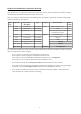
201 2 Set Zero
0 sigint Only applicable to Voltage & Current Inputs
3,16
203 1 Set Zero Divisor
2 0…4 Only applicable to Voltage & Current Inputs
3, 6,16
204 2 Set Span
10000 sigint Only applicable to Voltage & Current Inputs
3,16
206 1 Set Span Divisor
2 0…4 Only applicable to Voltage & Current Inputs
3, 6,16
207 2 Bar Low
* sigint
3,16
209 1 Bar Low Divisor
* 0…4
3, 6,16
210 2 Bar High
* sigint
3,16
212 1 Bar High Divisor
* 0…4
3, 6,16
213 2 Alarm1 Setpoint
* sigint Only applicable if Option fitted
3,16
215 1 Alarm1 Setpoint Divisor
* 0…4
3, 6,16
216 2 Alarm1 Hysteresis
* sigint
3,16
218 1 Alarm1 Hysteresis Divisor
* 0…4
3, 6,16
219 2 Alarm2 Setpoint
* sigint
3,16
221 1 Alarm2 Setpoint Divisor
* 0…4
3, 6,16
222 2 Alarm2 Hysteresis
* sigint
3,16
224 1 Alarm2 Hysteresis Divisor
* 0…4
3, 6,16
225 2 4/20 O/P Zero
* sigint
3,16
227 1 4/20 O/P Zero Divisor
* 0…4
3, 6,16
228 8 4/20 O/P Span
* sigint
3,16
230 1 4/20 O/P Span Divisor
* 0…4
3, 6,16
* = Default values are input type dependent
10