
User's Manual

3.Operation
UP Plus 2 User Manual 46
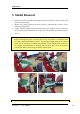
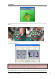
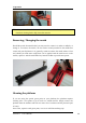
After the calibration model is printed, measure the X1 and X2 length, as shown in the pictures
below.
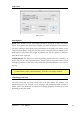
Open the ―Calibrate‖ box form the ―3D Print‖ menu and enter the measured X1 and X2 values
into the appropriate boxes.
IMPORTANT NOTE: Before you enter any new calibration values, always click the ―Reset‖
button, otherwise the new values get added to the old ones. Before you enter any new values, the
bar at the very top of the screen should read: XY: 0.00 deg / XZ: 0.00 deg.
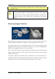
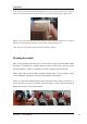
Next, take down the Front Centre ‗L‘ shaped component, and measure its deviation. Put the exact