
User's Manual

5
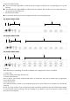
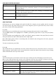
are the Selected Port LEDs:
The On Line LEDs light RED to indicate that the computer attached to the corresponding port is up and
running.
The Selected LEDs light GREEN to indicate that the computer that attached to the corresponding port is
the one that has the KVM focus.
1. Port Selection Switches
Press a switch button to access the computer attached to its corresponding port.
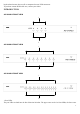
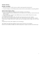
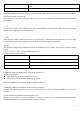
AS-3104DU REAR VIEW
1 2 3 4
AS-3108DU REAR VIEW
1 2 3 4
AS-3116DU REAR VIEW
1 2 3 4
1. Reset
When KVM has no responding, use needle or ballpoint pen to plug into the hole to reset KVM.
2. Power Jack
The power adapter cable plugs into this jack.
3. Console Port Selection
Ports to plug in your monitor, keyboard and mouse are found here. Each port is marked with an appropriate
icon to indicate itself.
4. CPU Port Section
The cables that link the switch to your computers plug in here. Each CPU port is comprised of a KVM data
connector.
NOTE: The shape of these 15-pin connectors has been specifically modified so that only KVM cables designed
to work with this switch can plug in. Do NOT attempt to use ordinary 15-pin VGA connector cables to link
these ports to the computes.