InHand Networks Edge Computing Gateway IG502 Quick Installation Manual InHand Networks www.inhandnetworks.com Version: V1.0 December, 2020 Copyright © 2020. All rights are reserved by InHand Networks and its licensors. Without the written permission of the Company, no unit or individual is allowed to excerpt, reproduce or transmit in any form part or all of the contents in the manual.
Content 1. Preface.................................................................................................................................................................1 2. Packing List ........................................................................................................................................................ 1 2.1. Panel .....................................................................................................................................................
1. Preface This document describes how to install and operate the edge computing gateway IG502 series products of Beijing InHand Networks Technology. Before using these products, confirm the product model and the number of accessories inside the package, and purchase a SIM card from the local network operator. 2. Packing List Each edge computing gateway product is delivered with accessories (such as standard accessories) frequently used at the customer site.
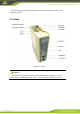
The following sections describe the panel, structure, and dimensions of the edge computing gateway. 2.1. Panel Figure 2-1 IG502 Caution The IG502 series product is applicable to multiple panel appearances, as they have the same installation method. Refer to the actual product during operation.
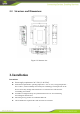
2.2. Structure and Dimensions Figure 2-2 Structure size 3. Installation Precautions: ⚫ ⚫ ⚫ ⚫ ⚫ Power supply requirements: 24 V DC (12–48 V DC). Environment requirements: operating temperature –25°C to 75°C; storage temperature – 40°C to 85°C; relative humidity 5% to 95% (non-condensing). The temperature on the device surface may be high. Install the device in a restricted area and assess the surrounding environment.
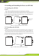
3.1. Installing and Uninstalling the Device on a DIN-Rail 3.1.1. Installing with a DIN-Rail Procedure: Step 1: Select an installation place and reserve enough space for installation. Step 2: Insert the upper part of the DIN rail seat onto the DIN rail. Grab the lower end of the device and revolve it upward in the direction indicated by arrow 2 with gentle force, to insert the DIN rail seat onto the DIN rail. Check that the device is installed reliably on the DIN rail, as shown in Figure 3-1 on the right.
3.2. Installing and Uninstalling the Device in Wall-mounted Mode 3.2.1. Installing in Wall-mounted Mode Procedure: Step 1: Select an installation place and reserve enough space for installation. Step 2: Install the wall mounting bracket on the back of the device by using a screwdriver, as shown in Figure 3-3.
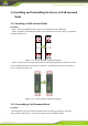
3.3. Installing a SIM Card IG502 supports Dual SIM card.
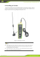
3.4. Installing an Antenna Revolve the movable part of the metal SMAJ interface with gentle force until it cannot be revolved, in which state the outer thread of the antenna connection cable is invisible. Do not wring the antenna with force by grabbing the black plastic cover. Figure 3-4 Installing an Antenna Note ⚫ IG502 supports dual antenna: ANT antenna and AUX antenna. The ANT antenna sends and receives data.
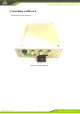
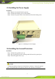
3.5. Installing the Power Supply Procedure: Step 1: Remove the terminal from the gateway. Step 2: Unfasten the locking screw on the terminal. Step 3: Connect the power cable to the terminal and fasten the locking screw. Figure 3-5 Installing the Power Supply 3.6. Installing the Ground Protection Procedure: Step 1: Unfasten the ground screw cap. Step 2: Put the ground loop of the cabinet ground cable onto the ground post. Step 3: Fasten the ground screw cap.
3.7. Connecting the Network Cable Connect the gateway to a PC directly by using the Ethernet cable. Figure 3-3 Network connection 3.8. Connecting Terminals Terminals provide the RS232 and RS485 interface modes. Connect cables to the corresponding terminals before using the interfaces. During installation, remove the terminals from the device, unfasten the locking screws on the terminals, connect cables to the corresponding terminals, and fasten the screws. Sort the cables in order.
4. Configuring Network Connection for a Wireless Gateway 4.1. Connecting to the Gateway Step 1: By default, the IP address of FE 0/1 on IG502 is 192.168.1.1; the IP address of FE 0/2 on IG502 is 192.168.2.1. This document uses the FE 0/2 port to access the IG502 as an example. Set the PC’s IP address to be on the same subnet with FE 0/2.
Method 2: Set a fixed IP address Select Use the following IP address, enter an IP address (By default,any from 192.168.2.2 to 192.168.2.254), subnet mask (By default,255.255.255.0), default gateway (By default,192.168.2.1), and DNS server address, and click OK.
4.2. Logging in to the Gateway Connect the PC to the gateway directly by using the network cable, start the web browser, enter https://192.168.2.1 in the address bar, and press Enter to jump to the web login page. Enter the user name (default: adm) and password (default: 123456), and click OK or press Enter to access the web configuration page. Figure 4-2 Login gateway Web management interface 4.3. Connect IG502 to Internet Step 1: Insert the SIM card.
When the network connection status is Connected and an IP address has been allocated, the IG502 has been connected to the Internet with the SIM card.