User manual EPC LX EPC LX nautic CiS-Nr.: 360.610.0370 Reg 10530/0408 Version 1.1/06.10 © Elektronik-Systeme LAUER GmbH & Co.
Elektronik Systeme LAUER GmbH & Co. KG P.O Box 1465 D-72604 Nürtingen Operating instructions: Issue: Editor: EPC LX & EPC LX nautic 06.2010 Mutter Operating instructions, manuals and software are copyrighted. All rights are reserved. Copying, duplicating, translating, transcribing en bloc or partially is prohibited. An exception is the making of a software back up copy for private use. • We reserve the right to make amendments to the manual without prior notice.
User tips Please read the manual prior to using for the first time and keep it in a safe place for future use. Target group The documented information in this manual refers to the appliance, place of use, transport, storage, assembly, use and maintenance. This manual is directed to the following target groups: • User • Service technicians/maintenance technicians Especially observe the chapter „safety instructions and general instructions“. Knowledge of PC and Microsoft-operating systems are assumed.
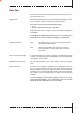
User tips Icons The following icons are used in the manual to mark certain paragraphs: Danger Means that death or severe injury will occur when the relevant precautionary measures are not taken Caution Means that death or severe injury may occur when the relevant precautionary measures are not taken.
Contents User tips 3 Contents 5 Preamble 6 1 Product description 1.1 Operating panel 1.2 Slot panel 1.3 Ports 1.3.1 Compact FLASH Slot 1.3.2 VGA-/COM1-/PS/2 port 1.3.3 Ethernet, USB 1.4 Back side 7 8 8 9 9 9 10 10 2 Start-up 2.1 Power supply 2.2 Grounding diagram 2.3 Installation 2.4 Switch on the PC 11 11 12 12 12 3 Service 3.1 Replacing the external CFC 3.2 Replacing the internal CFC 3.3 Replacing the fuse 3.
Preamble Elektronik-Systeme LAUER GmbH & Co. KG Kelterstraße 59 D-72669 Unterensingen Tel. +49 (0) 7022 / 9660-0 Fax +49 (0) 7022 / 9660-103 www.lauer-hmi.de Our philosophy Elektronik-Systeme Lauer is one of the leading suppliers in the area of industrial automation. For more than 30 years, Lauer has developed and marketed innovative HMI solutions for operating and monitoring machinery and equipment.
1 Product description The EPC LX line is a compact, mechanically robust, fanless industrial panel PC. This embedded PC system comes in two variants, either as just a CPU box or together with a high-contrast industrial color TFT display. It is available in the following display sizes: 6.4" 8.4", 10.4", 12" and 15". The analog resistive touch screen is the basis of communication between human and machine.
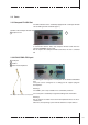
1.1 Operating panel 1 Color TFT resistive touch display 6.4", 8.4", 10.4",12" or 15" 1 1.2 Slot panel 0-8 © Elektronik-Systeme Lauer GmbH & Co KG • Kelterstr.59 • 72669 Unterensingen • Tel.
1.3 Ports 1.3.1 Compact FLASH Slot The EPC industrial PC is standardly equipped with a Compact FLASH slot according to CFA standards (Type 1). Position of the Compact FLASH slot 1 Captive screw 1 Warning! In connection with the EPC, only Compact FLASH cards from the company SANDISK may be used. Do not replace the Compact FLASH card unless the PC is switched off! 1.3.
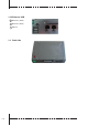
1.3.3 Ethernet, USB 1 Ethernet 1 (RJ45) 2 Ethernet 2 (RJ45) 3 3 USB 1/2 2 1 1.4 Back side 0-10 © Elektronik-Systeme Lauer GmbH & Co KG • Kelterstr.59 • 72669 Unterensingen • Tel.
2 Start-up 2.1 Power supply Warning! Only operate the embedded PC using protective extra-low voltage according to EN60950! The transformer must meet the EN60742 standard! Check the power supply to ensure it corresponds to the type plate. Prior to system start-up, check all cable connections. Make sure that all voltages and signals meet the relevant specifications. The 0V supply voltage connection to the housing (earth) is a lowimpedance connection.
2.2 Grounding diagram In order to reliably prevent electrical disruptions, please note the following points: • Connect the PC and control cabinet as close to a central grounding point as possible. • Make sure inductive connection between the computer and the control cabinet is as low as possible. • All data cables connected to the computer have to be shielded cables. • The shields have to be grounded on both ends. There must be a low-impedance connection between the connected systems.
3 Service Tools All you need to assemble the PC is a 2.0 hexagon socket as well as a 5.5 socket wrench. A small screwdriver and pliers are also helpful (see illustrations). Preparation Disconnect the PC from the power supply! Danger! Make sure that your electro-static underlay is not able to damage the front of the EPC. Open PC Only authorized personnel may perform work on the open PC. Within the warranty period, the hardware may only be updated with memory and plug-in cards.
3.1 Replacing the external CFC To replace the external CFC, loosen the locking system using a socket wrench. Then turn the locking bracket upward to replace the CFC. 0-14 © Elektronik-Systeme Lauer GmbH & Co KG • Kelterstr.59 • 72669 Unterensingen • Tel.
3.2 Replacing the internal CFC To replace the internal CFC, remove the cover. Loosen the screws indicated in the illustration and remove the cover plate. The internal CFC slot is then visible. Press on the release levers (see arrows) and replace the CFC. Afterwards, simply screw the cover plate back on. © Elektronik-Systeme Lauer GmbH & Co KG • Kelterstr.59 • 72669 Unterensingen • Tel.
3.3 Replacing the fuse If the fuse has to be replaced, it can easily be removed using a pair of pliers. Replacing a new fuse T2,5A (item no.: 200.140.0110). 0-16 © Elektronik-Systeme Lauer GmbH & Co KG • Kelterstr.59 • 72669 Unterensingen • Tel.
3.4 Changing the battery If the battery needs to be replaced, you have to remove the back cover plate. To do so, loosen the screws as shown. Remove the back cover plate. The battery can be conveniently removed by hand. Please note that the BIOS settings may disappear when changing the battery. © Elektronik-Systeme Lauer GmbH & Co KG • Kelterstr.59 • 72669 Unterensingen • Tel.
Insert the new lithium 3V battery (item no.: 200.300.0070) with lettering facing up and screw the back plate back on firmly. 0-18 © Elektronik-Systeme Lauer GmbH & Co KG • Kelterstr.59 • 72669 Unterensingen • Tel.
T Technical data T1 Mechanical dimensions Air circulation To dissipate the heat emanating from the PC, 100 mm on three sides of the PC must be kept clear so air can freely circulate. T1.1 EPC LX 640 exterior/installation dimensions Front plate Width Height 211 mm 156 mm Cut out dimensions Width Height 197 mm 142 mm Installation depth 70 mm Weight approx. 1 kg Front panel cut-out for installation W x H cut-out 197.0 mm x 142.0 mm 1. Type of attachment: with 6 pieces.
T1.2 EPC LX 640 Unit dimensions view of the unit underneath lateral view unit rear view lateral view view of the equipment top side 0-20 © Elektronik-Systeme Lauer GmbH & Co KG • Kelterstr.59 • 72669 Unterensingen • Tel.
T1.3 EPC LX 840 Exterior/installation dimensions Front plate Width Height 252 mm 190 mm Cut out dimensions Width Height 232 mm 170 mm Installation depth 61 mm Weight approx. 1.9 kg © Elektronik-Systeme Lauer GmbH & Co KG • Kelterstr.59 • 72669 Unterensingen • Tel.
T1.4.1 EPC LX 840 Unit dimensions view of the unit underneath lateral view unit rear view lateral view view of the equipment top side 0-22 © Elektronik-Systeme Lauer GmbH & Co KG • Kelterstr.59 • 72669 Unterensingen • Tel.
Data sheet EPC-GX 840tc nautic T1.4.2 EPC LX 840 nautic Unit dimensions with Dual CAN IXKAT with Dual CAN IXXAT (optional) view of the unit underneath lateral view unit rear view lateral view view of the equipment top side © Elektronik-Systeme LAUER GmbH & Co. KG • Kelterstr. 59 • 72669 Unterensingen • Tel. 07022/9660-0 • Fax 07022/9660-103 © Elektronik-Systeme Lauer GmbH & Co KG • Kelterstr.59 • 72669 Unterensingen • Tel.
Data sheet EPC-GX 840tc nautic T1.4.3 EPC LX 840 nautic Unit dimensions with integrated Buzzer with integrated buzzer (optional) view of the unit underneath lateral view unit rear view lateral view view of the equipment top side © Elektronik-Systeme LAUER GmbH & Co. KG • Kelterstr. 59 • 72669 Unterensingen • Tel. 07022/9660-0 • Fax 07022/9660-103 0-24 © Elektronik-Systeme Lauer GmbH & Co KG • Kelterstr.59 • 72669 Unterensingen • Tel.
T1.5 EPC LX 1000 Exterior/installation dimensions Front plate Width Height 318 mm 244 mm Cut out dimensions Width Height 303 mm 228 mm Installation depth 77 mm Weight approx. 2.8 kg © Elektronik-Systeme Lauer GmbH & Co KG • Kelterstr.59 • 72669 Unterensingen • Tel.
T1.6.1 EPC LX 1000 Unit dimensions view of the unit underneath lateral view unit rear view lateral view view of the equipment top side 0-26 © Elektronik-Systeme Lauer GmbH & Co KG • Kelterstr.59 • 72669 Unterensingen • Tel.
T1.6.2 EPC LX 1000 nautic Unit dimensions view of the unit underneath lateral view unit rear view lateral view view of the equipment top side © Elektronik-Systeme Lauer GmbH & Co KG • Kelterstr.59 • 72669 Unterensingen • Tel.
T1.7 EPC LX 1200 Exterior/installation dimensions 0-28 Front plate Width Height 364 mm 296 mm Cut out dimensions Width Height 345 mm 277 mm Installation depth 77 mm Weight approx. 2.8 kg © Elektronik-Systeme Lauer GmbH & Co KG • Kelterstr.59 • 72669 Unterensingen • Tel.
T1.8 EPC LX 1200 Unit dimensions view of the unit underneath lateral view unit rear view lateral view view of the equipment top side © Elektronik-Systeme Lauer GmbH & Co KG • Kelterstr.59 • 72669 Unterensingen • Tel.
T1.9 EPC LX 1500 Exterior/installation dimensions Front plate Width Height 452 mm 357 mm Cut out dimensions Width Height 429 mm 334 mm Installation depth 77 mm Weight approx. 5.0 kg Front view Front dimensions W x H 452.0 x 357.0 mm Tolerance 0,2 mm Front panel cut-out for installation W x H cut-out 429.0 mm x 334.0 mm Space for holding blocks around 15 mm Space total W x H 459.0 mm x 364.0 mm 0-30 © Elektronik-Systeme Lauer GmbH & Co KG • Kelterstr.59 • 72669 Unterensingen • Tel.
T1.10 EPC LX 1500 Unit dimensions view of the unit underneath lateral view unit rear view lateral view view of the equipment top side © Elektronik-Systeme Lauer GmbH & Co KG • Kelterstr.59 • 72669 Unterensingen • Tel.
T2 Electrical data Power supply DC Operating voltage 24 V ± 20%, reverse polarity protected Fuse 2,5 A delay Power failure buffering time 1 ms bei 19,2 V (Ub-20%) Display Display Resolution Charging rate EPC LX Box EPC LX 640 EPC LX 840 / nautic EPC LX 1000 / nautic EPC LX 1200 EPC LX 1500 Touch resistive CPU unit CPU: System Memory: Chipset: I/O Chipset: BIOS: Battery: SSD: Display Chipset: On Board AMD Geode LX 800/700(533MHz) CPU 200-pin DDR SDRAM 1G
T3 Environmental conditions Surrounding temperature Operating Operating storage 0 ... 50° C 0 ... 55° C for nautic Versions -20 ... 60° C Humidity Operating storage 10 ... 75%, non-condensing 10 ...