EPC GEmbedded PC Reg 10497/0604 User Manual CiS No.: 360.610.0070 Version 1/06.04 © Systeme Lauer GmbH & Co.
Systeme Lauer GmbH & Co KG Postfach 1465 D-72604 NürtingenGermany User Manual: Issued: Author: EPC G Embedded PC June, 2004 Jung Operating instructions, manuals and software are protected by copyright laws. All rights reserved. Copying, duplicating, translating, or converting these materials in whole or in part is prohibited. An exception is made in the case of preparing a backup copy of the software for personal use. • The manual is subject to change without prior notification.
Information for Users Please read this manual before using the product for the first time, and be sure to keep it where you can make use of it later. Unless where explicitly referred to the versions Economy Unit or Business Unit, the description applies for all units. Intended audience The manual has been written for users who are familiar with PC systems and automation technology. Conventions used in this manual [KEY] Keys the user has to press on the keyboard are represented in square brackets, e.g.
Table of Contents Information for Users 0-3 Table of Contents 0-4 Company 0-5 Contact 0-6 1 Product Description Control side ..................................................................... 1.1.1 EPC G Touch .......................................................... 1.1.2 EPC G Key ............................................................. 1.2 Rear side .......................................................................... 1-1 1-1 1-1 1-1 1-2 Commissioning Power supply ...............
Company Elektronik-Systeme LAUER GmbH & Co. KG Kelterstraße 59 D-72669 UnterensingenGermany Tel. +49 (7022) 9660-0 Fax. + 49 (7022) 9660-274 Our philosophy Systeme LAUER is a reliable partner who thinks and acts internationally.
Contact Support Telephone: E-mail: +49 (7022) 9660–209 support@systeme-lauer.de In case of support enquiries, please have the serial number of the device ready ! Please access our Download Forum to find current drivers, software, drivers, manuals, … and novelties at http://forum.systeme-lauer.de/ Sales Telephone: E-mail: In addition, we offer +49 (7022) 9660-0 Sales@systeme-lauer.de ... training and technical courses in our modern training center, or, if you prefer, in your company.
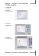
1 Product Description 1.1 Control side 1.1.1 EPC G Touch 1 Color TFT-Display 10,4“, 12,1“ or 15“ with Resistiv Touch 1 1.1.2 EPC G Key 2 Color TFT-Display 10,4“ with Resistiv Touch 2 3 Color TFT-Display 12,1“ with Resistiv Touch 3 © Systeme Lauer GmbH & Co KG • Kelterstr.59 • 72669 Unterensingen • Tel.
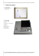
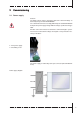
1 Product Description 4 Color TFT-Display 15“ with Resistiv Touch 5 Front plate V2A 4 5 1.2 Rear side 6 7 8 9 aJ aA aB aC 1-2 COM 1 / COM 2 VGA PS/2 Mouse / PS/2 keyboard USB 1 / 2 LAN 1 / 2 Grounding screw Power supply Compact Flash aC 6 aA 7 9 8 aJ aB © Systeme Lauer GmbH & Co KG • Kelterstr.59 • 72669 Unterensingen • Tel.
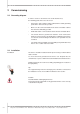
2 Commissioning 2.1 Power supply Caution! The EPC G must only be operated at protective extra-low-voltage as defined by European standard EN60950! The control transformer must comply with European standard EN60742! Compare the power supply voltage with the voltage specified on the type label. All cable connections must be tested before commissioning the system. You must ensure that all the voltages and signals correspond to the relevant specifications.
2 Commissioning 2.2 Grounding diagram In order to ensure a safe diversion of electric interferences, the following points have to be observed: • Connect the device and the switch cabinet with a central grounding point via the shortest route possible. • Make sure the connection between the device and switch cabinet has the lowest inductivity possible. • All the data cables connected to the device must be shielded cables. • The shields must be grounded on both the ends.
T Technical data T1 Mechanical dimensions Free spaces To ensure that heat generated in the device can dissipate into the environment, a space of 50 mm must be maintained around the device! T1.1 EPC G 1000 Outer/Mounting dimensions Front plate Width Height 318 mm 244 mm Cutout dimensions Width Height 303 mm 228 mm Mounting depth 119,5 mm. Weight approx.
T Technical data T1.2 EPC G 1000 Unit dimensions Bottom view of device Side view Rear view of device Side view Top view of device T-2 © Systeme Lauer GmbH & Co KG • Kelterstr.59 • 72669 Unterensingen • Tel.
T Technical data T1.3 EPC G 1200 Outer/Mounting dimensions Front plate Width Height 364 mm 296 mm Cutout dimensions Width Height 345 mm 277 mm Mounting depth 111,5 mm. Weight approx. 6,0 kg 8x Bohrhole Ø 4,6 mm Type of attachment: 8 pieces of nut/mother M4, 8 pieces of wearing parts M4 and 8 pieces of toothed washers M4. © Systeme Lauer GmbH & Co KG • Kelterstr.59 • 72669 Unterensingen • Tel.
T Technical data T1.4 EPC G 1200 Unit dimensions Bottom view of device Side view Rear view of device Side view Blick auf die Geräteoberseite T-4 © Systeme Lauer GmbH & Co KG • Kelterstr.59 • 72669 Unterensingen • Tel.
T Technical data T1.5 EPC G 1500 Outer/Mounting dimensions Front plate Width Height 452 mm 357 mm Cutout dimensions Width Height 429 mm 334 mm Mounting depth 124,5 mm Weight approx.76,5 kg Type of attachment: 10 pieces of nut/mother M4, 10 pieces of wearing parts M4 and 10 pieces of toothed washers M4. 10x Bohrhole Ø 4,6 mm © Systeme Lauer GmbH & Co KG • Kelterstr.59 • 72669 Unterensingen • Tel.
T Technical data T1.6 EPC G 1500 Unit dimensions Bottom view of device Side view Rear view of device Side view Top view of device T-6 © Systeme Lauer GmbH & Co KG • Kelterstr.59 • 72669 Unterensingen • Tel.
T Technical data T1.7 EPC G 1500 V2A Outer/Mounting dimensions Front plate Width Height 407 mm 316 mm Cutout dimensions Width Height 393 mm 303 mm Mounting depth 126 mm Weight approx. 7,0 kg Type of attachment: With 8 retaining blocks made of aluminum or plastic with M5x30, DIN 914 set screws,with tip and hexagon socket, galvanized. © Systeme Lauer GmbH & Co KG • Kelterstr.59 • 72669 Unterensingen • Tel.
T Technical data T1.8 EPC G 1500 V2A Unit dimensions Bottom view of device Side view Rear view of device Side view Top view of device T-8 © Systeme Lauer GmbH & Co KG • Kelterstr.59 • 72669 Unterensingen • Tel.
T Technical data T1.9 EPC G 1000k Outer/Mounting dimensions Front plate Width Height 410 mm 266 mm Cutout dimensions Width Height 387 mm 243 mm Mounting depth 120 mm. Weight approx. 6,5 kg Type of attachment: With 8 retaining blocks made of aluminum or plastic with M5x30, DIN 914 set screws,with tip and hexagon socket, galvanized. © Systeme Lauer GmbH & Co KG • Kelterstr.59 • 72669 Unterensingen • Tel.
T Technical data T1.10 EPC G 1000k Unit dimensions Bottom view of device Side view Rear view of device Side view Top view of device T-10 © Systeme Lauer GmbH & Co KG • Kelterstr.59 • 72669 Unterensingen • Tel.
T Technical data T1.11 EPC G 1200k Outer/Mounting dimensions Front plate Width Height 483 mm 310 mm Cutout dimensions Width Height 452 mm 292 mm Mounting depth 114,5 mm Weight approx. 7,0 kg Type of attachment: With 10 retaining blocks made of aluminum or plastic with M5x30, DIN 914 set screws,with tip and hexagon socket, galvanized. © Systeme Lauer GmbH & Co KG • Kelterstr.59 • 72669 Unterensingen • Tel.
T Technical data T1.12 EPC G 1200k Unit dimensions Bottom view of device Side view Rear view of device Side view Top view of device T-12 © Systeme Lauer GmbH & Co KG • Kelterstr.59 • 72669 Unterensingen • Tel.
T Technical data T2 Electrical data Power supply Operating voltage Power consumption Display 24 V ± 15 %, protected against reverse polarity approx. 2 A EPC G 1000 TFT-Display 800 x 600 Pixel, 65536 colors, 10,4“, CFL background illumination EPC G 1200 TFT-Display 800 x 600 Pixel, 65536 colors, 12,1“, CFL background illumination EPC G 1500 TFT-Display 1024 x 768 Pixel, 16 Mio. colors, 15“, CFL background illumination Operating temperature range 0 ...
T Technical data T3 Ambient conditions Ambient temperature Humidity Operation in case of vertical (standing) installation 0...45°C Storage -20 ... 60° C Operation/Storage 10 ...
T Technical data T4 Interfaces T4.1 Compact-FLASH-Slot In its standard configuration, the EPC devices are equipped with a Compact FLASH slot based on CFA standard (Type 1). Position of Compact-FLASH-Slots 1 Ejection lever 1 Caution! Compact FLASH cards manufactured by SANDISK only may be used in combination with the EPC! The compact FLASH card may be changed only when the device has been switched off ! T4.
T Technical data T4.3 Ethernet, USB, PS/2 1 Ethernet 1 / 2 (RJ45) 2 USB 1 / 2 3 PS2 Mouse/Keyboard 2 3 1 Caution! The PS/2 mouse and PS/2 keyboard may be plugged or unplugged only when the device is switched off. Otherwise these input devices are not recognized by the operating system! A maximum current of 100 mA may be drawn from the two USB interfaces! External USB devices which require a higher supply current have to provide this current themselves! T4.4 Cassette option 1 Bus module cassette (opt.