Cover_MAEN979B.
Foreword EPC C2D Nautic Installation Manual Foreword The EPC C2D Nautic series consists of enhanced Panel IPCs, compatible with the toughest of maritime environments. Shock and vibration resistant and functional throughout comprehensive temperature changes, the series features a robust hard-disk drive, fanless CPU and Windows XP as the standard operating system.
Contents Contents 1 Safety Precautions................................................................................... 5 1.1 Nautic Approvals and Certificates ....................................................... 5 1.2 General ............................................................................................... 6 1.3 During Installation.............................................................................. 7 1.4 During Use ..............................................................
Contents 7 Service .................................................................................................. 31 7.1 Introduction ......................................................................................31 7.1.1 Tools .................................................................................................31 7.1.2 Preparation........................................................................................31 7.1.3 Opening the EPC............................................
Safety Precautions 1 Safety Precautions Both the installer and the owner and/or operator of the EPC must read and understand this installation manual. 1.1 Nautic Approvals and Certificates The EPC C2D Nautic series are certified according to the following list. Some approvals are in progress. Please visit our web site for the latest information.
Safety Precautions 1.2 General – The EPC is intended for industrial use only. – The EPC is constructed for naval applications and for indoor use according to IEC 60945. – Read the safety precautions carefully. – Check the delivery for transportation damage. If damage is found, notify the supplier as soon as possible. – Do not use the EPC in an environment with high explosive hazards. – The supplier is not responsible for modified, altered or reconstructed equipment.
Safety Precautions 1.3 During Installation – The EPC is designed for stationary installation on a plane surface, where the following conditions are fulfilled: • • • • no high explosive risks no strong magnetic fields no direct sunlight no large, sudden temperature changes – Install the EPC according to the accompanying installation instructions. – Ground the EPC according to the accompanying installation instructions. – Only qualified personnel may install the EPC.
Safety Precautions 1.5 Service and Maintenance – Only qualified personnel should carry out repairs. – The agreed warranty applies. – Before carrying out any cleaning or maintenance operations, disconnect the equipment from the electrical supply. – Clean the display and surrounding front cover with a soft cloth and mild detergent. – Replacing the battery incorrectly may result in explosion. Only use batteries recommended by the supplier. 1.
Product Naming 2 Product Naming The naming of the computers is constructed with a number of parameters that indicate the characteristics of each model, for example EPC T170 C2D Nautic AC according to below: EPC T 170 C2D Nautic AC Computer series Optional touch screen Screen size Processor type Main usage Type of power supply There is a variant without display; EPC C2D Box Nautic AC: EPC C2D Box Nautic AC Computer series Processor type No display Main usage Type of power supply Beij
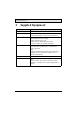
Supplied Equipment 3 Supplied Equipment Part Description CD; operating system CD with operating system. CD; driver software Driver software CD for all pre-installed components such as mother board, touch screen, keyboard etc. Power cable Standard power cable (European or US standard) for units with 230 V AC power supply. Length: approximately 3.0 m. 24 V DC units are delivered without cable. A variety of cables are available separately.
Compass Safety Distance 4 Compass Safety Distance The EPC C2D Nautics are certified according to EN 60945 for bridge applications. The tests include a compass safety distance test. Electrical devices, such as the EPC C2D Nautic, must be kept in a safe distance to a compass in operation according to the following table: Compass type Steering compass Minimum distance to the EPC C2D Nautic 1 meter in all directions Emergency compass Standard compass 1.
Description of Parts 5 Description of Parts 5.1 EPC C2D Nautic The EPC C2D Nautic consists of a Front unit and a PC unit. These are installed in the same way independent of the display size. Front unit PC unit The EPC Box C2D Nautic consists of the PC unit only.
Description of Parts 5.2 Display Display sizes 15", 17" and 19" are available, as well as the EPC Box C2D Nautic without display. Power button USB port Dimmer buttons The front includes a USB-port under hatch, a power button with a LED, and a set of dimmer buttons.
Description of Parts The power LED can assume the following statuses: LED Description Green Red - Normal operation No input signal available or the screen is in energy saving mode The EPC is turned off or the screen is dimmed to 0 (lowest value, darkest possible) 5.
Description of Parts 5.4 Motherboard The EPC C2D Nautic has 2 SODIMM slots for main storage and 2 PCI-slots. Further details on the motherboard can be found in a separate manual, included in the delivery. Note: The quality of the memory module may influence the system stability. When updating the memory module, or adding a second one, please only use memory modules approved by Beijer Electronics. Memory modules are electrostatic sensitive components.
Description of Parts 5.6 Power Supply The EPC C2D Nautic is available with 230 V AC or 24 V DC power system. 230 V AC Power Supply Connection with Integrated Fuse Fuse 1 A Earth screw 24 V DC Power Supply Connection Fuse 6.3 A Earth screw The power supply for 24 V DC is carried out via a double-pole connector (Phoenix MST BT 2,5/2). The EPC C2D Nautic is certified for the connection to protective grounded power supply according to EN60950.
Description of Parts 5.7 Earthing System The following items have to be observed to guarantee a safe dissipation of electronic interference: – The EPC and switch board have to be connected to the nearest possible central earthing point. – Make sure of a possibly low inductive connection between EPC and switch board. – All data cables connected to the EPC have to be of the shielded type. – The screens have to be earthed on both sides. A low ohm connection between the connected systems is essential.
Description of Parts 5.9 ATX Remote Connector The ATX remote terminal is a double-pole connector close to the red ATX power switch button. It is parallel connected to the button. An external push-button switch or a relay contact can be connected to the ATX remote connector. 5.10 Compact Flash Memory Card An external Compact Flash memory card can be used for data storage. Some EPC models also allow mounting an internal Compact Flash memory card as a boot-up device, or for data storage.
Operation 6 Operation 6.1 Operating System The EPC C2D Nautic is delivered with Windows XP operating system. The operating system and other programs are installed on drive “C:”. Drive “D:” contains all data required for a new installation (drivers and operation system) and may also be used for user data (beneficial for example for data backup).
Operation 6.2 Default BIOS Settings The BIOS settings may need to be checked or altered if the system becomes instable. To start the setup: Switch on the EPC and press the [DEL] button, according to the first screen image. Selecting Load Optimized Defaults loads the following settings.
Operation Menu Menu item Advanced Chipset Features System Bios Cacheable Integrated Peripherals On Chip IDE Device Integrated Peripherals Onboard Device Integrated Peripherals Super IO Integrated Peripherals USB Device Setting Power Management Setup Setting Enabled On Chip Frame Buffer Size 8 MB DVMT Mode DVMT DVMT / Fixed Memory Size 128 MB Boot Display Auto Panel Number 15" 17" 19" 12: 1024x768 24 bit 13: 1280x1024 48 bit 13: 1280x1024 48 bit IDE HDD Block Mode Enabled IDE DMA transfer
Operation Menu PNP / PCI Configuration Frequency Voltage Control 22 Menu item Init Display First Setting Onboard Reset Configuration Data Disabled PCI/VGA Palette Snoop Disabled INT Pin 1 Assignment Auto INT Pin 2 Assignment Auto INT Pin 3 Assignment Auto INT Pin 4 Assignment Auto INT Pin 5 Assignment Auto INT Pin 6 Assignment Auto INT Pin 7 Assignment Auto INT Pin 8 Assignment Auto Auto Detect PCI / clk Enabled Spread Spectrum Disabled Beijer Electronics, MAEN979B
Operation 6.3 Important Items Regarding Software Installation The included driver CD includes all drivers needed for a successful reinstallation of the EPC. Since the EPC is not equipped with a CD/DVD player, an external USB CD/DVD player has to be used. The drivers are also available on the “D:” drive. When the CD is loaded, a menu is displayed for selection of driver installation, displaying manuals etc. Follow the steps below in the specified order, when reinstalling the system: 1.
Operation 6.4 Graphic Board Installation After finalizing the Windows installation (chipset driver) and re-starting the system, terminate the automatic driver search for the graphic board driver and use the installation CD instead. Note: The graphic driver will be installed twice. 5. After finishing the installation and re-starting the EPC, the following entries are available under the Display icon in the Control Panel, or in the display properties.
Operation 6.5 Touch Screen Installation Note: Make sure to use a touch driver of version 6.31.a or higher. 1.
Operation 2. Accept the license agreement.
Operation 3. Select Autodetect or manually select the technical connection data.
Operation 4. Press Finish and follow the instructions for a re-start. 5. After a re-start of the operating system you will find Hampshire Control Panel among the programs. 6. Calibrate the touch screen with your finger or with a rounded pointed touch pen.
Operation 6.6 Installation of LAN-/Network Card After installing the operating system and the chipset driver, the system automatically creates a link to a network connection. You will find a network icon on the lower right-hand side of the task bar. 1. To install the second network card, follow the instructions on the driver CD. 2. Confirm each installation step and re-start the EPC at the end of the installation. 3. After the re-start two new network icons appear in the right hand side lower task bar. 4.
Operation 30 Beijer Electronics, MAEN979B
Service 7 Service 7.1 Introduction Only spare parts recommended by Beijer Electronics may be used. 7.1.1 Tools You can carry out the disassembly and assembly with an 2.5 mm Allen key and a Phillips head screwdriver, size 3. 7.1.2 Preparation Disconnect the EPC from the power supply. Attention! Deadly Peril! Make sure that your electrostatic pad does not damage the front panel of the EPC. 7.1.3 Opening the EPC All operations to the opened EPC may only be carried out by authorized personnel.
Service 7.2 Changing the Fan Filter The fan filter will have to be replaced regularly, especially in dusty environments. Gently remove the fan cover, remove the filter and insert a new filter in its place. 7.3 PCI-board Installation To install a PCI-board the right hand side part of the rear enclosure has to be removed. 1. To open the enclosure remove the marked seven screws with an Allen key. After removing the screws the enclosure can be easily removed.
Service The picture of the opened EPC below shows the board holder (1) and the 2 PCIslots (2). 1 2 2. Remove the cover of the desired slot to insert your PCI-board, by removing the screw and pulling out the cover.
Service 3. Remove the board holder by unscrewing the two marked screws. 4. Insert the PCI-board, if necessary bend the slot bracket a little bit. Please ensure a correct fit at the rear edge (3) of the slot and make sure the metal bracket goes into the groove (4).
Service 5. Mount your PCI-board and make sure to properly tighten the screw. 6. Re-assemble the board holder and tighten the two screws properly.
Service 7. To ensure an optimal use of the board holder, we recommend that you put wide boards in the lower slot and narrow boards in the upper. This way the support can be used in the correct way. 5 Note: If two wide boards are used, the short support (5) can be removed. 7.4 Cable Fixing Points When connecting interface cables such as RS232, USB, LAN or VGA, the cables must be fixed at the cable fixing points, to avoid that the cables loosen because of vibrations.
Technical Data 8 Technical Data The EPC T150/T170/T190 C2D Nautic models have touch screens; the EPC 150/170/190 C2D Nautic models have an antireflective glass. Parameter EPC T150/150 C2D Nautic EPC T170/170 EPC T190/190 C2D Nautic C2D Nautic Size, W x H x D, 412 x 351 x 142.5 430 x 390 x complete with front mm 142.5 mm plate 483.2 x 444 x 142.
Technical Data Parameter EPC T150/150 C2D Nautic EPC T170/170 EPC T190/190 C2D Nautic C2D Nautic Power consumption at rated voltage 85 VA Fuse 1 AT (230 V AC) or 6.3 AT (24 V DC) EPC C2D Box Nautic Power supply options 115-230 V AC ± 15%. 1 A max (switch on peak 30 A). 24 V DC ± 15%. 3 A max (switch on peak 15 A). Active area of display 304.1 x 228.1 mm 337.9 x 270.3 mm Pixels 1024 x 768 1280 x 1024 Pixel pitch (RGB) 0.297 x 0.297 mm 0.264 x 0.264 mm 376.3 x 301.1 mm 0.294 x 0.294 mm Max.
Drawings 9 Drawings 9.1 EPC T150/150 C2D Nautic Front View 412 222 333 351 206 394 64.5 6 x hole Ø 6.
Drawings 9.2 EPC T150/150 C2D Nautic Cut Out Drawing 324 333 +1 0 222 Cut out dimensions: 369.0 x 324.0 mm, tolerance +1 mm. Space for mounting screws on all sides: 15 mm = needed space 399.0 x 354.0 mm. 369 +1 0 55.5 6 x bore holes Ø 6.5 mm 197 197 394 Front plate 412.0 x 351.0 mm, tolerance: ±0.2 mm. Mounting method: 6 x M6x25 steel screws DIN 6912. Screws and o-ring seals are included. Max. 8 mm thick mounting frame.
Drawings 9.3 EPC T150/150 C2D Nautic Outline Drawings Bottom view 205.7 36.5 24.5 387.5 375.5 80.3 R3 Rear view Side view 18 67.5 112.8 238.
Drawings 9.4 EPC T170/170 C2D Nautic Front View 430 200 374 180 390 115 414 105 8 x bore holes Ø 6.
Drawings 9.5 EPC T170/170 C2D Nautic Cut Out Drawing 180 364 +1 0 374 Cut out dimensions: 396.0 x 364.0 mm, tolerance +1 mm. Space for mounting screws on all sides: 15 mm = needed space 426.0 x 394.0 mm. 92 8 x bore holes Ø 6.5 mm 200 396 +1 0 414 Front plate 430.0 x 390.0 mm, tolerance: ±0.2 mm. Mounting method: 8 x M6x25 steel screws DIN 6912. Screws and o-ring seals are included. Max. 8 mm thick mounting frame.
Drawings 9.6 EPC T170/170 C2D Nautic Outline Drawings Bottom view 412 384.5 89.3 45.5 214.7 18 R3 Rear view Side view 15 109.5 154.8 280.2 361.
Drawings 9.7 EPC T190/190 C2D Nautic Front View 230 235 426 444 104.6 126.6 104.4 8 x bore holes Ø 6.5 mm 126.6 230 Beijer Electronics, MAEN979B 483.2 126.
Drawings 9.8 EPC T190/190 C2D Nautic Cut Out Drawing 426 416 +1 0 235 Cut out dimensions: 438.0 x 416.0 mm, tolerance +1 mm. Space for mounting screws on all sides = 15 mm - needed space 468.0 x 446.0 mm. 90.4 8 x bore holes Ø 6.5 mm 230 438 +1 0 465.2 Front plate 483.2 x 444.0 mm, tolerance: ±0.2 mm. Mounting method: 8 x M6x25 screws DIN 6912. Screws and o-ring seals are included. Max. 8 mm thick mounting frame.
Drawings 9.9 EPC T190/190 C2D Nautic Outline Drawings Bottom view 458.1 241.3 12 25.1 115.9 72.1 411.1 R3 Rear view Side view 16.5 146.5 191.8 317.2 398.
Drawings 9.10 EPC Box C2D Nautic Outline Drawings Bottom view 339 169.2 10 104 114 43.8 Side view 382 Rear view 276 255.5 244 234 244 220.5 119 Ø7 182.7 144 57.3 Ø8.5 44 55.5 34 44 20.5 12 374.5 389 131.5 0 14.5 0 Mounting method: 6 x M4x12 steel screws DIN 912 or 4 x M6x12 steel screws DIN 912. Screws are included. 48 Beijer Electronics, MAEN979B 276 264 Ø4.
Cover_MAEN979B.fm Page 2 Tuesday, August 24, 2010 11:13 AM Head Office Subsidiaries Sweden Beijer Electronics Products AB Box 426 201 24 Malmö, SWEDEN Tel: +46 40 35 86 00 Fax: +46 40 93 23 01 info@beijerelectronics.com Germany Elektronik-Systeme Lauer GmbH & Co. KG Kelterstraße 59 72669 Unterensingen, GERMANY Tel.: +49 70 22/96 60 0 Fax: +49 70 22/96 60-103 info@lauer-hmi.com China Beijer Electronics Co. Ltd Room 201, Buildning B, No.