User Guide Revision 1.
User Guide Revision 1.
User Guide Revision 1.
User Guide Revision 1.121 Declaration of Conformity: Beijer Electronics hereby states that the BFI‐P2 product range conforms to the relevant safety provisions of the Low Voltage Directive 2006/95/EC and the EMC Directive 2004/108/EC and has been designed and manufactured in accordance with the following harmonised European standards: EN 61800‐5‐1: 2003 Adjustable speed electrical power drive systems. Safety requirements. Electrical, thermal and energy.
User Guide Revision 1.12 1. Introduction ...................................................................................................................................7 1.1. 2. 2.1. 2.2. 2.3. 2.4. 2.5. 3. Digital Input Configuration Parameter P1‐13 ......................................................................................................................................... 35 Extended Parameters ..........................................................................................
User Guide Revision 1.121 1. Introduction 1.1. Important safety information Please read the IMPORTANT SAFETY INFORMATION below, and all Warning and Caution information elsewhere. Danger : Indicates a potentially hazardous situation Danger : Indicates a risk of electric shock, which, if not other than electrical, which if not avoided, could result avoided, could result in damage to the equipment and in damage to property. possible injury or death.
User Guide Revision 1.12 2. General Information and Ratings 2.1. Part Number Construction and Definition The model number of each BFI‐P2 is constructed according to the following system.
User Guide Revision 1.121 2.3.
User Guide Revision 1.12 3. Mechanical Installation 3.1. General • • • • • • The Drive should be mounted in a vertical position only, on a flat, flame resistant, vibration free mounting using the integral mountingholes or DIN Rail clip (Frame Size 2 only). The Drive must be installed in a pollution degree 1 or 2 environment only. Do not mount flammable material close to the Drive Ensure that the minimum cooling air gaps, as detailed in section 3.5 and 3.
User Guide Revision 1.121 3.4.2.
User Guide Revision 1.12 3.4.3. IP66 Units ØI ØJ D B A E H G F Note : Unit shown is a non‐switched unit with optional OLED display Drive Size 2 3 A / Height mm 257 310 B mm 220 277 D mm 200 252 E mm 28.5 33.4 F / Depth mm 238 256 G / Width mm 188 211 Mounting Bolt Sizes All Frame Sizes 4 x M4 Tightening Torques Control Terminal Torque Settings : Power Terminal Torque Settings : All Sizes : Frame Size 2 : 0.8 Nm 1.2 – 1.5 Nm www.beijerelectronics.
User Guide Revision 1.121 3.4.4. IP40 Units G ØI A C B D F E Drive Size A B C D E F G H I J Weight mm mm mm mm mm mm mm mm mm mm kg 8 2000 1925 1950 733 516 500 350 406 35 19 270 Control Terminal Torque Settings: Power Terminal Torque Settings: All Sizes: 0.8Nm All Sizes: 50Nm www.beijerelectronics.
User Guide Revision 1.12 3.5. Guidelines for Enclosure mounting (IP20 Units) • • • • • IP20 drives are suitable for use in pollution degree 1 environments, according to IEC‐664‐1. For pollution degree 2 or higher environments, drives should be mounted in a suitable control cabinet with sufficient ingress protection to maintain a pollution degree 1 environment around the drive. Enclosures should be made from a thermally conductive material.
User Guide Revision 1.121 3.7. Guidelines for mounting (IP55/IP66 Units) • • • • Before mounting the drive, ensure that the chosen location meets the environmental condition requirements for the drive shown in section 10.
User Guide Revision 1.12 3.8. Guidelines for mounting (IP40 Units) • • • • • Before mounting the drive, ensure that the chosen location meets the environmental condition requirements for the drive shown in section 10.
User Guide Revision 1.121 3.9.2. Frame Size 4 Using a suitable flat blade screwdriver, rotate the two retaining screws indicated until the screw slot is vertical. 3.9.3. Frame Size 5 Using a suitable flat blade screwdriver, rotate the four retaining screws indicated until the screw slot is vertical. Terminal Cover Release Screws 3.9.4. Frame Size 6 and 7 Remove the two screws indicated, lift the cover forwards and off.
User Guide Revision 1.12 3.10. Removing the Terminal Cover 3.10.1. Frame Size 8 Open Access to Control Terminal Wiring and Options Module Slot Access to Power and Motor Wiring 3.11. Routine Maintenance The drive should be included within the scheduled maintenance program so that the installation maintains a suitable operating environment, this should include: • Ambient temperature is at or below that set out in the “Environment” section. • Heat sink fans freely rotating and dust free.
User Guide Revision 1.121 4. Electrical Installation 4.1. Grounding the Drive This manual is intended as a guide for proper installation. The manufacturer cannot assume responsibility for the compliance or the non‐compliance to any code, national, local or otherwise, for the proper installation of this drive or associated equipment. A hazard of personal injury and/or equipment damage exists if codes are ignored during installation.
User Guide Revision 1.12 4.1.2. Grounding Guidelines The ground terminal of each Drive should be individually connected DIRECTLY to the site ground bus bar (through the filter if installed). Drive ground connections should not loop from one drive to another, or to, or from any other equipment. Ground loop impedance must confirm to local industrial safety regulations. To meet UL regulations, UL approved ring crimp terminals should be used for all ground wiring connections.
User Guide Revision 1.121 4.4. Operation of 3 Phase drives from a Single Phase Supply A special function of Drive allows all drives designed for operation on 3 phase supplies to be operated on a single phase supply of the correct rated voltage at up to 50% of the nominal capacity. For Example, Model Number ODP‐2‐64450‐3KA4N can be operated on a single phase supply, 380 – 480 volts, with the maximum output current limited to 45 Amps The supply should be connected to the L1 and L2 terminals of the drive. 4.
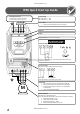
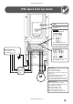
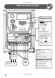
User Guide Revision 1.12 4.8. Control Terminal Wiring • • • • All analog signal cables should be suitably shielded. Twisted pair cables are recommended. Power and Control Signal cables should be routed separately where possible, and must not be routed parallel to each other Signal levels of different voltages e.g. 24 Volt DC and 110 Volt AC, should not be routed in the same cable. Maximum control terminal tightening torque is 0.5Nm 4.9. Connection Diagram 4.9.1.
User Guide Revision 1.121 4.10. Safe Torque Off Safe Torque OFF will be referred to as “STO” through the remainder of this section. 4.10.1.
User Guide Revision 1.12 4.10.4. “STO“ Operation When the “STO” inputs are energised, the “STO” function is in a standby state, if the drive is then given a “Start signal/command” (as per the start source method selected in P1‐13) then the drive will start and operate normally. When the “STO” inputs are de‐energised then the STO Function is activated and stops the drive (Motor will coast), the drive is now in “Safe Torque Off” mode.
User Guide Revision 1.121 4.10.7. “STO“Electrical Installation The “STO” wiring shall be protected from inadvertent short circuits or tampering which could lead to failure of the “STO” input signal, further guidance is given in the diagrams below. In addition to the wiring guidelines for the “STO” circuit below, section 4.1.1 “Recommended installation for EMC compliance. should also be followed.
User Guide Revision 1.12 4.10.10. Enabling the “STO” Function The “STO” function is always enabled in the drive regardless of operating mode or parameter changes made by the user. 4.10.11.
User Guide Revision 1.121 5. Managing the Keypad The drive is configured and its operation monitored via the keypad and display. 5.1.
User Guide Revision 1.12 5.3. Advanced Keypad Operation Short Cuts Function When Display shows... Press...
User Guide Revision 1.121 5.5. Keypad Layout and Function – Optional OLED Keypad An optional Multi Language OLED display keypad may be specified at the time of order, option code –Tx. This option is not available for IP20 drives. OLED Display Control Keypad Main Displayed Parameter Provides access to the drive parameters, Shows which of the selectable and also allows control of the drive parameters is currently being shown on when Hand operation is selected. the main display, e.g.
User Guide Revision 1.12 5.8. Changing the Language on the OLED Display P2 Hold down the Start and and Up keys for >1s Use the Up and Down arrows to select a language. Press the Navigate button to select. 5.9. Resetting Parameters to Factory Default Settings LED Display Press and hold the Keys for at least 2 seconds The display will show P-Def Press the key OLED Display Hold down the Up, Down, Start and Stop keys for >2s The display shows P‐Def. Drive is returned to User Standard settings.
User Guide Revision 1.121 5.10. Terminal Control When delivered, the Drive is in the factory default state, meaning that it is set to operate in terminal control mode and all parameters have the default values as indicated in section6. • Connect the drive to the supply, ensuring the correct voltage and fusing / circuit breaker protection – see section 10.2. • Connect the motor to the drive, ensuring the correct star/delta connection for the voltage rating ‐ see section 4.6.
User Guide Revision 1.12 5.11. Keypad Control To allow the Drive to be controlled from the keypad in a forward direction only, set P1‐12 =1: • Connect the drive to the supply, ensuring the correct voltage and fusing / circuit breaker protection – see section 10.2. • Connect the motor to the drive, ensuring the correct star/delta connection for the voltage rating ‐ see section 4.6.
User Guide Revision 1.121 6. Parameters 6.1. Parameter Set Overview The Parameter set consists of 6 groups as follows: • Group 0 – Read Only Monitoring Parameters • Group 1 – Basic Configuration Parameters • Group 2 – Extended Parameters • Group 3 – PID Control Parameters • Group 4 – High Performance Motor Control Parameters • Group 5 –Field Bus Parameters When the Drive is reset to factory defaults, or is in its factory supplied state, only Group 1 Parameters can be accessed.
P1‐11 P1‐12 P1‐13 P1‐14 User Guide Revision 1.12 V/F Mode Voltage Boost 0.0 Drive Rating Dependent % Voltage boost is used to increase the applied motor voltage at low output frequencies, in order to improve low speed and starting torque. Excessive voltage boost levels may result in increased motor current and temperature, and force ventilation of the motor may be required.
User Guide Revision 1.121 7. Digital Input Functions 7.1.
User Guide Revision 1.
User Guide Revision 1.121 8. Extended Parameters 8.1. Parameter Group 2 ‐ Extended parameters Par P2‐01 P2‐02 P2‐03 P2‐04 P2‐05 P2‐06 P2‐07 P2‐08 P2‐09 P2‐10 P2‐11 P2‐12 P2‐13 Parameter Name Minimum Maximum Default Units Preset / Jog Frequency / Speed 1 P1‐02 P1‐01 5.0 Hz / Rpm Preset / Jog Frequency / Speed 2 P1‐02 P1‐01 10.0 Hz / Rpm Preset / Jog Frequency / Speed 3 P1‐02 P1‐01 25.0 Hz / Rpm Preset / Jog Frequency / Speed 4 P1‐02 P1‐01 50.0 (60.
User Guide Revision 1.12 Par P2‐14 P2‐15 P2‐16 P2‐17 P2‐18 P2‐19 P2‐20 Parameter Name Analog Output 2 (Terminal 11) Format Minimum See Below Default ‐ U 0-10 = 0 to10V. U 10-0 = 10 to 0V, A 0-20 = 0 to 20mA A 20-0 = 20to 0mA A 4-20 = 4 to 20mA A 20-4 = 20 to 4mA User Relay 1 Output (Terminals 14, 15 & 16) Function select 0 13 1 ‐ Selects the function assigned to Relay Output 1.
User Guide Revision 1.121 Par P2‐21 P2‐22 P2‐23 P2‐24 P2‐25 P2‐26 P2‐27 P2‐28 P2‐29 P2‐30 P2‐31 P2‐32 Parameter Name Minimum Maximum Default Units Display Scaling Factor ‐30.000 30.000 0.000 ‐ Display Scaling Source 0 2 0 ‐ P2‐21 & P2‐22 allow the user to program the Drive to display an alternative output unit scaled from an existing parameter, e.g. to display conveyer speed in metres per second based on the output frequency. This function is disabled if P2‐21 is set to 0.
User Guide Revision 1.
User Guide Revision 1.121 8.2. Parameter Group 3 – PID Control Par P3‐01 P3‐02 P3‐03 P3‐04 P3‐05 P3‐06 P3‐07 P3‐08 P3‐09 P3‐10 P3‐11 P3‐12 P3‐13 P3‐18 Parameter Name Minimum Maximum Default Units PID Proportional Gain 0.1 30.0 1.0 ‐ PID Controller Proportional Gain. Higher values provide a greater change in the drive output frequency in response to small changes in the feedback signal. Too high a value can cause instability PID Integral Time Constant 0.0 30.0 1.0 s PID Controller Integral Time.
User Guide Revision 1.12 8.3. Parameter Group 4 – High Performance Motor Control Incorrect adjustment of parameters in menu group 4 can cause unexpected behaviour of the motor and any connected machinery. It is recommended that these parameters are only adjusted by experienced users. Par P4‐01 P4‐02 P4‐03 P4‐04 P4‐05 P4‐06 P4‐07 P4‐08 Parameter Name Minimum Maximum Default Units Motor Control Mode 0 2 2 ‐ Selects the motor control method. An autotune must be performed if setting 0 or 1 is used.
User Guide Revision 1.121 8.4. Parameter Group 5 – Communication Parameters Par. P5‐01 P5‐02 P5‐03 P5‐04 P5‐05 P5‐06 P5‐07 P5‐08 P5‐12 P5‐13 P5‐14 Name Minimum Maximum Default Units Drive Fieldbus Address 0 63 1 ‐ Sets the fieldbus address for the Drive CAN Open Baud Rate 125 1000 500 kbps Sets the baud rate when CAN Open communications are used Modbus RTU Baud Rate 9.6 115.2 115.
User Guide Revision 1.12 8.5. Parameter Group 0 – Monitoring Parameters (Read Only) Par P0‐01 P0‐02 P0‐03 P0‐04 P0‐05 P0‐06 P0‐07 P0‐08 P0‐09 P0‐10 P0‐11 P0‐12 P0‐13 P0‐14 P0‐15 P0‐16 P0‐17 P0‐18 P0‐19 P0‐20 P0‐21 P0‐22 P0‐23 P0‐24 P0‐25 Description Units Analog Input 1 Applied Signal Level % Displays the signal level applied to analog input 1 (Terminal 6) after scaling and offsets have been applied.
User Guide Revision 1.121 Par P0‐26 P0‐27 P0‐28 P0‐29 P0‐30 P0‐31 P0‐32 P0‐33 P0‐34 P0‐35 P0‐36 P0‐37 P0‐38 P0‐39 P0‐40 P0‐41 P0‐42 P0‐43 P0‐44 P0‐45 P0‐46 P0‐47 P0‐48 P0‐49 P0‐50 Description Units Energy Consumption kWh Meter kWh Displays the amount of energy consumed by the drive in kWh. When the value reaches 1000, it is reset back to 0.0, and the value of P0‐27 (*MWh meter) is increased. Energy Consumption MWh Meter MWh Displays the amount of energy consumed by the drive in MWh.
User Guide Revision 1.12 9. Serial communications 9.1. RS‐485 communications An RJ45 connector located on the drive allows the user to connect the drive to a Modbus RTU network or CANBus via a wired connection. The electrical signal arrangement of the RJ45 connector is shown as follows: CAN‐ CAN+ 0 Volt Remote Keypad / PC Connection ‐ Remote Keypad / PC Connection + +24 Volt Remote Keypad Power Supply RS 485‐ Modbus RTU RS 485+ Modbus RTU 9.2. Modbus RTU Communications 9.2.1.
User Guide Revision 1.121 9.2.2. Modbus Control & Monitoring Registers The following is a list of accessible Modbus Registers available in the Drive. • When Modbus RTU is configured as the Fieldbus option, all of the listed registers can be accessed. • Registers 1 and 2 can be used to control the drive providing that Modbus RTU is selected as the primary command source (P1‐12 = 4) and no Fieldbus Option Module is installed in the drive Option Slot.
User Guide Revision 1.12 10.Technical Data 10.1. Environmental Ambient temperature range Operational : ‐10 … 50 °C (IP20 Units), 40°C (IP55 Units), 30°C (IP55, 90kW / 150HP units) Storage : ‐40 °C … 60 °C Max altitude for rated operation : 1000m Derating above 1000m (to 4000m max) : 1% / 100m Relative Humidity : < 95% (non condensing) Note : Drive must be Frost and moisture free at all times Installation above 2000m is not UL approved 10.2.
User Guide Revision 1.121 380 ‐ 480 Volt (+ / ‐ 10%) 3 Phase Input, 3 Phase Output kW (400V) HP (460V) Nominal Input Current 0.75 1.5 2.2 4 5.5 7.5 11 15 18.5 22 30 37 45 55 75 90 110 132 160 200 250 1 2 3 5 7.5 10 15 20 25 30 40 50 60 75 100 150 175 200 200 200 200 2 5.1 7.7 11.7 14.1 18.3 27 29 39.7 48.6 61.5 72.3 91.2 116.9 150.2 176.5 217.2 255.7 302.
User Guide Revision 1.12 10.3. Additional Information for UL Approved Installations The drive is designed to meet the UL requirements. In order to ensure full compliance, the following must be fully observed. Input Power Supply Requirements Supply Voltage 200 – 240 RMS Volts for 230 Volt rated units, + /‐ 10% variation allowed.
User Guide Revision 1.121 10.4. Derating Information Derating of the drive maximum continuous output current capacity is require when • Operating at ambient temperature in excess of 40°C / 104°F • Operating at Altitude in excess of 1000m/ 3281 ft • Operation with Effective Switching Frequency higher than the minimum setting The following derating factors should be applied when operating drives outside of these conditions 10.4.1.
User Guide Revision 1.12 11.Troubleshooting Fault Code Description No Fault Corrective Action Displayed in P0‐13 if no faults are recorded in the log 01 Brake channel over current OL-br 02 Brake resistor overload O-I 03 Instantaneous over current on drive output. Excess load on the motor. I.t-trp 04 Drive has tripped on overload after delivering >100% of value in P1‐08 for a period of time.
User Guide Revision 1.121 Fault Code th-Flt data-F 16 Description Instantaneous over current on drive output. Faulty thermistor on heatsink. 17 Internal memory fault. 4-20F 18 4‐20mA Signal Lost data-E 19 Internal memory fault.
User Guide Revision 1.12 Notes: www.beijerelectronics.
User Guide Revision 1.121 Notes: www.beijerelectronics.
User Guide Revision 1.12 www.beijerelectronics.