User Guide Revision 1.12 IP55 Quick Start Up Guide Mechanical Mounting Information can be found in section 3.6. HVAC Display (Status, Diagnostics, and Programming) Keypad Operation can be found in section 5.
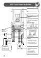
User Guide Revision 1.12 IP66 Quick Start Up Guide Mechanical Mounting Information can be found in section 3.5. HVAC Display (Status, Diagnostics, and Programming) Applies to Switched version only In-built Isolator: Mains Power On / Off Keypad Operation can be found in section 5.5 Hardware Link the terminals as shown, optionally through switch contacts to enable drive operation RJ45 Connector Control Terminal Configuration based on factory settings Fuses or MCB Check Drive Rating info in section 13.4.
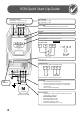
User Guide Revision 1.12 IP20 Quick Start Up Guide AC Supply Connection 3 Phase Units : Connect L1 L2 L3, PE 1 Phase Units : Connect L1, L2, PE Fuses or MCB Supply Voltage 200 – 240 Volts + / - 10% 380 – 380 Volts + / - 10% Fuses or MCB o Check the Drive Rating Information in section 13.4 Help Card Display Information can be found in section 5.1 Keypad Operation can be found in section 5.
User Guide Revision 1.12 Declaration of Conformity: The Manufacturer hereby states that the HVAC Inverter H2 product range conforms to the relevant safety provisions of the Low Voltage Directive 2006/95/EC and the EMC Directive 2004/108/EC and has been designed and manufactured in accordance with the following harmonised European standards: EN 61800-5-1: 2003 Adjustable speed electrical power drive systems. Safety requirements. Electrical, thermal and energy.
User Guide Revision 1.12 1. Introduction ................................................................................................................................ 8 1.1. 2. 2.1. 2.2. 3. Pump Staging – DOL Cascade ............................................................................................................................................ 30 Pump Staging – Multiple Drive Cascade ........................................................................................................
User Guide Revision 1.12 10.1. Digital Input Configuration Parameter P1-13 ................................................................................................................... 49 11. Extended Parameters ................................................................................................................ 50 11.1. 11.2. 11.3. 11.4. 11.5. 11.6. 11.7. 11.8. 11.9. Parameter Group 2 - Extended parameters .................................................................................
User Guide Revision 1.12 1. Introduction 1.1. Important safety information Please read the IMPORTANT SAFETY INFORMATION below, and all Warning and Caution information elsewhere. Danger : Indicates a risk of electric shock, which, if not Danger : Indicates a potentially hazardous situation avoided, could result in damage to the equipment and other than electrical, which if not avoided, could result possible injury or death. in damage to property.
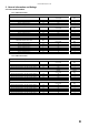
User Guide Revision 1.12 2. General Information and Ratings 2.1. Drive model numbers 2.1.1. IP20 Enclosed Units 200-240V ±10% - 1 Phase Input kW Model with Filter kW Output Current (A) Frame Size BFI-H2-22-0043-1KF12-xx BFI-H2-22-0070-1KF12-xx BFI-H2-22-0105-1KF12-xx 0.75 1.5 2.2 4.3 7 10.5 2 2 2 kW Model Number with Filter kW Output Current (A) Frame Size BFI-H2-22-0043-3KF12-xx BFI-H2-22-0070-3KF12-xx BFI-H2-22-0105-3KF12-xx BFI-H2-32-0018-3KF12-xx BFI-H2-32-0240-3KF12-xx 0.75 1.5 2.2 4.0 5.
User Guide Revision 1.12 2.1.3. IP55 Enclosed Units 200-240V ±10% - 3 Phase Input kW Model Number with Filter kW Output Current (A) Frame Size BFI-H2-44-0240-3KF1N-xx BFI-H2-44-0300-3KF1N-xx BFI-H2-44-0460-3KF1N-xx BFI-H2-54-0610-3KF1N-xx BFI-H2-54-0720-3KF1N-xx BFI-H2-64-0900-3KF1N-xx BFI-H2-64-1100-3KF1N-xx BFI-H2-64-1500-3KF1N-xx BFI-H2-64-1800-3KF1N-xx BFI-H2-74-2020-3KF1N-xx BFI-H2-74-2480-3KF1N-xx 5.5 7.5 11 15 18.
User Guide Revision 1.12 3. Mechanical Installation 3.1. General The drive should be mounted in a vertical position only on a flat, flame resistant vibration free mounting using the integral holes. The drive must be installed in a pollution degree 1 or 2 environment only. Do not mount flammable material close to the drive Ensure that the minimum cooling air gaps, as detailed in section 3.8 thru 3.
User Guide Revision 1.12 3.5. Mechanical dimensions and mounting – IP66 Units ØH ØI D B A E H G Drive Size 2 3 A mm 257 310 F B in 10.12 12.20 mm 220 277 C in 8.66 10.89 Control Terminal Torque Settings: Power Terminal Torque Settings: mm - D in - mm 200 252 E in 7.87 9.90 mm 28.5 33.4 F in 1.12 1.31 G mm 257 310 2 3 in 10.12 12.20 H mm 220 277 in 8.66 10.89 I mm - in - mm 200 252 All Sizes: 0.8 Nm (7 lb-in) All Sizes: 1 Nm (8.85 lb-in) 3.6.
Control Terminal Torque Settings: Power Terminal Torque Settings: All Sizes: Frame Size 4: Frame Size 5: Frame Size 6: Frame Size 7: User Guide Revision 1.12 0.8 Nm (7 lb-in) 1.2 – 1.5 Nm 2.5 – 4.5 Nm 8 Nm 8 Nm 3.7. Mechanical dimensions and mounting – IP40 Units G ØH ØI A C B D F Drive Size A mm 8 E B in mm C in mm D in mm E in mm F in mm G in mm H in mm I in 2000 78.74 1925 75.79 1950 76.77 733 28.86 516 20.31 500 19.69 350 13.78 406 15.
User Guide Revision 1.12 3.8. Guidelines for Enclosure mounting (IP20 Units) Installation should be in a suitable enclosure, according to EN60529 or other relevant local codes or standards. Enclosures should be made from a thermally conductive material. Where vented enclosures are used, there should be venting above the drive and below the drive to ensure good air circulation – see the diagram below. Air should be drawn in below the drive and expelled above the drive.
User Guide Revision 1.12 3.10. Guidelines for mounting IP40 Units Before mounting the drive, ensure that the chosen location meets the environmental condition requirements for the drive shown in section 13.
User Guide Revision 1.12 3.11. Removing the Terminal Cover 3.11.1. Frame Size 2 Using a suitable flat blade screwdriver, rotate the two retaining screws indicated until the screw slot is vertical 3.11.3. Frame Size 4 Using a suitable flat blade screwdriver, rotate the two retaining screws indicated until the screw slot is vertical. 3.11.2. Frame Size 3 Using a suitable flat blade screwdriver, rotate the two retaining screws indicated until the screw slot is vertical 3.11.4.
User Guide Revision 1.12 3.11.5. Frame Size 6 Using a suitable flat blade screwdriver, rotate the two retaining screws indicated until the screw slot is vertical 3.11.6.
User Guide Revision 1.12 3.11.7.
User Guide Revision 1.12 3.12. Gland Plate and Lock Off The use of a suitable gland system is required to maintain the appropriate IP / Nema rating. Cable entry holes will need to be drilled to suit this system. Some guidelines sizes are defined below: Please take care when drilling to avoid leaving any particles within the product. Cable Gland recommended Hole Sizes & types: Min Gland Rating Hole Size Imperial Metric Size 2 IP66 3 x 22mm 3 PG13.5 3 x M20 Size 3 IP66 1 x 22mm and 2 x 28mm 1 PG13.
User Guide Revision 1.12 4. Electrical Installation 4.1. Grounding the Drive This manual is intended as a guide for proper installation. The Manufacturer cannot assume responsibility for the compliance or the non-compliance to any code, national, local or otherwise, for the proper installation of this drive or associated equipment. A hazard of personal injury and/or equipment damage exists if codes are ignored during installation.
User Guide Revision 1.12 4.2. Wiring Precautions Connect the drive according to section 4.3 and 4.4, ensuring that motor terminal box connections are correct. There are two connections in general: Star and Delta. It is essential to ensure that the motor is connected in accordance with the voltage at which it will be operated. For more information, refer to section 4.5 Motor Terminal Box Connection.
User Guide Revision 1.12 4.5. Motor Terminal Box Connections Most general purpose motors are wound for operation on dual voltage supplies. This is indicated on the nameplate of the motor This operational voltage is normally selected when installing the motor by selecting either STAR or DELTA connection. STAR always gives the higher of the two voltage ratings. Incoming Supply Voltage Motor Nameplate Voltages 230 230 / 400 Connection Delta 400 400 / 690 400 230 / 400 Star 4.6.
User Guide Revision 1.12 4.7. Control Terminal Wiring All analog signal cables should be suitably shielded. Twisted pair cables are recommended. Power and Control Signal cables should be routed separately where possible, and must not be routed parallel to each other Signal levels of different voltages e.g. 24 Volt DC and 110 Volt AC, should not be routed in the same cable. Maximum control terminal tightening torque is 0.5Nm 4.8. Connection Diagram 4.8.1.
User Guide Revision 1.12 5. Managing the Keypad The drive is configured and its operation monitored via the built in keypad and display.
User Guide Revision 1.12 5.3. Advanced Keypad Operation Short Cuts – Standard LED Keypad (IP20 Drives) Function Fast Selection of Parameter Groups Note : Parameter Group Access must be enabled P1-14 = 101 When Display shows... xxx Press...
User Guide Revision 1.12 Main Displayed Parameter Shows which of the selectable parameters is currently being shown on the main display, e.g. Motor Speed, Motor Current etc. Control Keypad Provides access to the drive parameters, and also allows control of the drive when Hand operation is selected. Navigate Button Used to display real-time information, to access and exit parameter edit mode and to store parameter changes Operating Information Provides a real time display of key operating information, e.g.
User Guide Revision 1.12 5.8. Resetting Parameters to Factory Default Settings – Standard OLED Keypad (IP55 and IP66 Drives) Hold down the Up, Down, Start and Stop keys for >2s The display shows P-Def. Drive is returned to factory settings. Press the Stop key Note: Parameters cannot be defaulted whilst P2-39=1 (parameter set locked). 5.9.
User Guide Revision 1.12 5.10. Changing the Language on the OLED Display – Standard OLED Keypad (IP55 and IP66 Drives) Hold down the Start, Navigate, and Up keys for >1s Use the Up and Down arrows to select a language. Press the Navigate button to select Language. 5.11. Selecting between Hand and Auto Control – Standard OLED Keypad (IP55 and IP66 Drives) A = Auto H = Hand The active control source is shown on the OLED display.
User Guide Revision 1.12 6. Commissioning 6.1. General The following guidelines apply to all applications 6.1.1.
User Guide Revision 1.12 7. HVAC Specific Feature Setup (Menu 8) The drive has several features inbuilt into the drive standard operating software that are specific to HVAC applications. The majority of parameters used in enabling and configuring these functions are contained within menu 8 (See section 11.7). This section is an explanation of the purpose and operation of each of these functions and guidelines on how each one can be configured. 7.1.
User Guide Revision 1.12 Set Basic parameters P1-01 to P1-10. Energy Optimiser P1-06 must remain disabled.
User Guide Revision 1.12 When the system is enabled the master drive will check the run time clocks for all drives in the network which are stored and maintained within menu 0 of the master drive. The first available drive with the lowest run time is automatically run first. At a predefined level additional drives / pumps are brought on-line in sequence to assist the running pumps.
User Guide Revision 1.12 P2-15 P2-18 Relay output 1 function select Relay output 2 function select 14 / 15 16 / 17 / 18 10 10 When the maintenance interval has expired and the scheduled service has been completed the service interval timer is reset by setting P6-25 = 1, Reset Service Indicator. The timer for the next service interval starts from the point at which the previous indication was reset.
User Guide Revision 1.12 A detection tolerance for the Load Profile Monitoring Function is set within parameter P8-07. Parameter P8-07 (Load Profile Monitoring Function Bandwidth) is set as a current (amps) value and is then applied to the standard operating profile stored within the drive to allow for acceptable variations in the motor current measurement. The value entered is applied symmetrically to the nominal current value so totally bandwidth is 2 x P8-07.
User Guide Revision 1.12 The Pump Cleaning cycle is defined by setting two segment speeds, a ramp time (used for acceleration and deceleration), and a segment time in the following parameters: Parameter Number P2-05 P2-06 P8-04 P8-05 Description Clean Speed 1 Clean Speed 2 Pump Cleaning Function Time Interval Pump Cleaning Function Ramp Time If either of the two Pump Cleaning Speeds are set to zero then that segment of the cleaning cycle is disabled.
User Guide Revision 1.12 Operational Overview: The time period to trigger the pump Stir function is entered into parameter P8-01 (Stir Function Integral Timer). When the drive enters into standby mode (see PID control, section 8) an internal timer is started. When the timer exceeds the user defined time limit set in P8-01 a preset motion profile is activated. When function execution is completed the drive returns immediately to standby mode.
User Guide Revision 1.12 The main selector switch selects between the following modes. System Off : Drive is powered off; Bypass contactor is off Bypass Control : Drive is powered off; Bypass contactor is on, motor running from bypass supply Drive Control : Drive is powered on; Bypass or Drive Output contactor selection is controlled by the drive When the Main Selector Switch is set to Drive Control, the drive input contactor is switched in such that the drive will power up.
User Guide Revision 1.12 Bypass Mode on Fault is enabled by setting parameter P8-11=1 (enabled). Once enabled the drive will switch to bypass mode in the event of a trip or fault occurring on the drive. When a trip occurs the drive will immediately open the drive output contactor (drive output already disabled due to trip), wait a time (defined by P8-13) and then close the bypass contactor.
User Guide Revision 1.12 P9-32: Fire Mode input source can be set via P9-32 to an available digital input. Advanced level security (default P1-14 = 201) is required to access menu 9 parameters The fire mode function is enabled once an input is assigned to activate fire mode. The logic selection for the fire mode input is configured through parameter P8-09 – Fire Mode Logic Select. It can be set to open active (0) or close active (1).
User Guide Revision 1.12 Set parameter P9-32 to an available digital input value. Note, P1-13 must be set to 0. Any other digital inputs required must also be configured through menu 9. If required, set either P2-15 or P2-18 = 9 to configure output relay 1 or output relay 2 to indicate fire mode active. 7.9.
User Guide Revision 1.12 The function uses the Boost Voltage on the drive reaching zero speed in order to create a current and maintain an appropriate temperature within the motor. The drive Standby Mode must be disabled so that the drive output is not automatically put into Standby following a period of operation with zero speed reference. The level of DC Injection Voltage applied to the motor is set in parameter P1-11 (V/F Boost Voltage).
User Guide Revision 1.12 8. PID Control Applications 8.1. Overview The PID Controller is a mathematical function designed to automate adjustments within a system and to eliminate the need for the machine operator to continuously pay attention to machine operation and to make manual adjustments.
User Guide Revision 1.12 8.2.3. PID Operating Mode Selection For default operation the drive response to an increase in feedback signal is to decrease motor speed and vice versa to adjust the feedback signal back to the set-point. This is referred to as ‘Direct Mode’ PID control. For example when pressure increases in a pumping system and the feedback signal increases then the drive response is to slow the pump to reduce the pressure.
User Guide Revision 1.12 point). For dynamic systems which respond quickly, the value will need to be shorter. Slow response systems, such as temperature control applications will require a correspondingly longer time setting. P3-03 Differential Time Constant: Range 0.00 to 1.00, Default 0.00 The differential time constant is also a time based function, this time modifying the PID output based on changes in the Set-point. In most applications, leaving the setting of P3-03 at zero will give good results.
User Guide Revision 1.12 The execution time for both the sleep and wake boost functions (P6-11 and P6-12) include the time taken to accelerate to the boost speed (P207 and P2-08) but not the time to accelerate or decelerate once the boost function ends. This is shown in the timing diagrams. When boost on sleep in activated the drive will automatically run the boost on sleep function whenever the drive is stopped / disabled.
User Guide Revision 1.12 8.4. PID Pipe Prime (Fill) Mode with Pipe Break Detection. Pump prime mode allows starting of the pump in a safely controlled manner, to ensure consistent filling and pressurisation of pipe work and systems. Low pressure warnings are ignored during priming to allow the system to prime correctly, whilst a failsafe timeout prevents the pump from continuing to run in the event of a failure to prime.
User Guide Revision 1.12 9. Parameters 9.1.
P1-11 P1-12 P1-13 P1-14 Voltage Boost User Guide Revision 1.12 0 15 – 30% 0.5 – 2.5% [Drive Dependent] [Drive Dependent] % Voltage boost is used to increase the applied motor voltage at low output frequencies, in order to improve low speed and starting torque. Excessive voltage boost levels may result in increased motor current and temperature, and force ventilation of the motor may be required.
User Guide Revision 1.12 10.Digital Input Functions 10.1.
User Guide Revision 1.12 11.Extended Parameters 11.1. Parameter Group 2 - Extended parameters Par P2-01 P2-02 P2-03 P2-04 P2-05 P2-06 P2-07 P2-08 P2-09 P2-10 P2-11 Note: Parameter Name Minimum Maximum Default Units Preset Speed 1 -P1-01 P1-01 5.
User Guide Revision 1.12 P2-12 P2-13 Note: P2-14 P2-15 Note: P2-16 P2-17 = 0 to10V, = 10 to 0V, = 0 to 20mA = 20to 0mA = 4 to 20mA = 20 to 4mA Analog Output 2 Function (Terminal 11) 0 11 9 Digital Output Mode. Logic 1 = +24V DC 0 : Drive Enabled (Running). Logic 1 when the drive is enabled (Running) 1 : Drive Healthy. Logic 1 When no Fault condition exists on the drive 2 : At Target Frequency (Speed).
User Guide Revision 1.12 P2-18 Note: P2-19 P2-20 P2-21 P2-22 Note: P2-23 P2-24 P2-25 P2-26 P2-27 P2-28 P2-29 Relay Output 2 Function (Terminals 17 & 18) 0 8 0 Selects the function assigned to Relay Output 2. The relay has two output terminals, Logic 1 indicates the relay is active, and therefore terminals 17 and 18 will be linked together. 0 : Drive Enabled (Running). Logic 1 when the motor is enabled 1 : Drive Healthy.
User Guide Revision 1.
P2-39 P2-40 User Guide Revision 1.12 Parameter Access Lock 0 1 0 : Unlocked. All parameters can be accessed and changed 1 : Locked. Parameter values can be displayed, but cannot be changed Extended Menu Access Code 0 9999 Defines the access code which must be entered in P1-14 to access parameter groups above Group 1 0 - 101 - 11.2.
User Guide Revision 1.12 P3-15 P3-16 P3-17 P3-18 nd 2 PID Digital Reference Value 0.0 100.0 0.0 % nd When P3-05 = 0, and the 2 digital reference is selected (see Digital Input Functions – Section 10.1) this parameter sets the preset digital reference (set-point) used for the PID Controller Pump Prime Time 0 600 0 Seconds A value other than zero in this parameter will automatically enable burst pipe protection function.
P5-08 P5-09 P5-10 P5-11 P5-12 P5-13 P5-14 User Guide Revision 1.12 Fieldbus Module PDO4 0 7 1 When using an optional Fieldbus interface, this parameter configures the parameter source for the 4th process data word transferred from the drive to the network master during cyclic communications: 0 : Output Power – Output power in kW to two decimal places, e.g. 400 = 4.00kW 1 : Output Power – Output power in kW to two decimal places, e.g. 400 = 4.
P6-10 P6-11 P6-12 P6-18 P6-22 P6-23 P6-24 P6-25 P6-26 P6-27 P6-28 P6-29 P6-30 User Guide Revision 1.12 PLC Function Enable 0 1 0 This parameter enables the PLC function support and must be set to 1 before any PLC program loaded into the drive will operate. When set to 0, the PLC program will be disabled. 0: Disabled 1: Enabled Speed Hold Time On Enable 0 250 0 Seconds Defines a time period for which the drive will run at Preset Speed 7 (P2-07) when the Enable signal is applied to the drive.
P8-05 Note: P8-06 P8-07 P8-08 Note: P8-09 P8-10 Note: P8-11 P8-12 P8-13 Note: P8-14 P8-15 P8-16 User Guide Revision 1.12 Clean Function Ramp Time 0.0 6000 30 Secs Independent ramp rate used only for the pump automatic cleaning function (see P8-03) when the motor is Accelerated as part of the cleaning cycle. For full detail of Clean function configuration see section 7.
P8-17 P8-18 P8-19 P8-20 Note: User Guide Revision 1.12 Assist Pump Start Speed P8-18 P1-01 0 Hz / RPM H2 drive upper speed Staging threshold. When the drive output increases beyond this threshold the next Staging pump is switch on. The Pump staging settle time must then expire before additional staging pumps can be brought on or off line. Priority for Staging pump switch on is always given to the pump with lowest run time accumulated.
User Guide Revision 1.12 11.9. Parameter Group 0 – Monitoring Parameters (Read Only) Par P0-01 P0-02 P0-03 P0-04 P0-06 P0-07 P0-08 P0-09 P0-10 P0-11 P0-13 P0-14 P0-16 P0-17 P0-19 P0-20 P0-21 P0-22 P0-23 P0-24 P0-25 P0-26 P0-27 P0-28 Parameter Name Minimum Maximum Default Units Analog Input 1 Value -100.0 100.0 % Displays the signal level applied to analog input 1 (Terminal 6) after scaling and offsets have been applied. Analog Input 2 Value 0.0 100.
User Guide Revision 1.12 P0-29 P0-30 P0-31 P0-32 P0-33 P0-34 P0-35 P0-36 P0-37 P0-38 P0-39 P0-40 Note: P0-41 P0-42 P0-43 P0-44 P0-45 P0-46 Note P0-47 P0-48 P0-49 P0-51 P0-52 P0-53 P0-54 Drive Type Displays the type details of the drive: Three entry display: First display = Frame size and input voltage level Second display = Power rating Third display = Output Phase Count Serial Number Displays the unique serial number of the drive.
User Guide Revision 1.12 P0-57 P0-58 P0-59 P0-60 P0-61 P0-63 P0-64 P0-65 P0-68 P0-69 P0-70 P0-71 P0-72 P0-73 P0-74 P0-75 P0-76 P0-77 P0-78 P0-79 P0-80 Ud / Uq Internal Value, Contact your local Drive Distributor Load Torque Profile Current Values A Parameter contains the 5 Current values measured during the Load Torque Characteristic Auto-Tune function.
User Guide Revision 1.12 12.Serial communications 12.1. RS-485 communications The drive has an RJ45 connector located within the wiring enclosure of the drive. This connector allows the user to set up a drive network via a wired connection. The connector contains two independent RS485 connections, one for manufacturer proprietary Protocol and one for Modbus RTU / BACnet. Both connections can be used simultaneously.
User Guide Revision 1.12 12.2.2. Modbus Control & Monitoring Registers The following is a list of accessible Modbus Registers available in the drive.
User Guide Revision 1.12 13.Technical Data 13.1. Environmental Ambient temperature range: Operational: IP20 -10 … 50C / Max 55C with de-rating IP40, IP55, IP66 -10 … 40C / Max 45C with de-rating -40 C … 60 C 1000m 1% per 100m above 1000m Maximum 2000m with UL approval Maximum 4000m without UL approval < 95% (non condensing) Storage: Max altitude for rated operation: Derating above 1000m: Relative Humidity: 13.2.
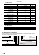
User Guide Revision 1.12 200 - 240 Volt (+ / - 10%) 3 Phase Input, 3 Phase Output kW HP Nominal Input Current A 0.75 1.5 2.2 4 5.5 7.5 11 15 18.5 22 30 37 45 55 75 1 2 3 5 7.5 10 15 20 25 30 40 50 60 75 120 5.7 8.4 13.1 17.3 25 32.9 54.1 69.6 76.9 92.3 116.9 150.2 176.5 211 267 Fuse Or MCB (Type B) Non UL UL (A) 10 10 16 20 32 40 63 80 100 125 160 200 200 250 315 10 10 15 20 30 35 60 80 100 125 150 175 200 225 300 mm Supply Cable Size AWG / kcmil 1.5 2.
User Guide Revision 1.12 13.5. Additional Information for UL Approved Installations Optidrive HVAC is designed to meet the UL requirements. In order to ensure full compliance, the following must be fully observed. Input Power Supply Requirements Supply Voltage 200 – 240 RMS Volts for 230 Volt rated units, + /- 10% variation allowed.
User Guide Revision 1.12 14.Parameter Change Tables The following tables can be used to enter parameter changes made to the drive as a result of commissioning and to provide future reference.
User Guide Revision 1.
User Guide Revision 1.12 15.Troubleshooting 15.1. Fault messages Fault Code No. OLED Message 00 No Fault 03 Over current trip . 04 05 06 07 08 09 10 11 12 13 14 15 18 error 4-20mA signal out of range 19 M/C processor data error 70 Corrective Action Displayed in P0-13 if no faults are recorded in the log Instantaneous over current on Fault Occurs on Drive Enable drive output.
User Guide Revision 1.12 Fault Code No. 20 21 OLED Message Description User Parameter Default User Parameter Defaults Motor PTC over heat Motor PTC Over Temperature Corrective Action User Parameter default has been loaded. Press the Stop key. Three button default – see section 5.9 The connected motor PTC device has caused the drive to trip (analog input 2 configured for PTC device).
User Guide Revision 1.12 82-H2MAN-BE_V1.