
Manual


7230 Hollister Avenue, Goleta, California 93117 | Tel: 805-968-0782 | Fax: 805-968-3154 | www.beisensors.com
9
Specication No.: 02135 Rev: 5-23-2013
PHD User Manual
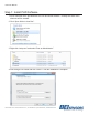
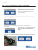
7. Dene four additional parameters for the part:
• Hysteresis– The Hysteresis option allows you to to
independently program the amount of hysteresis each output
will have. A value of zero degrees will give the minimum amount
of hysteresis and 11 degrees will give the maximum amount of
hysteresis. This value is most commonly set to zero.
• Travel (Deg)– The Travel option allows you to program the
rotational angle you want to resolve. Values from 1° to 360° are
valid, however the linearity of the output may be negatively impacted for angles less than
15°. It is possible to program a separate angle for each of the sensor’s outputs; however
a slightly different programming sequence from this example is required.
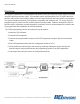
• Clamp Low and Clamp High– Allows you to independently set min/max percentage
limits for each output. These limits restrict each output from going beyond the limit
programmed. Clamp High and Low work exactly the same way for the Non-Ratio Metric
and PWM units as it does for the Ratiometric. For example assuming 5VDC is supplied to
the sensor’s input, the output would be as follows:
Clamp Low
(%)
Clamp High
(%)
Min/Max Vout
(V)
0 100 0/5
5 95 0.25/4.75
10 90 0.5/4.5
25 80 1.25/4
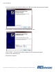
8. If PWM was selected as the Output Type two additional parameters must be set:
• PWM Frequency is the output frequency which the PWM unit will output
at, this value is CONSTANT and does not change with output location.
• PWM Polarity determines how the Duty Cycle
changes based on the position of the shaft.
• Rising Edge– 0% High at 0% position, 100% High at
100% position.
• Falling Edge– 0% High at 0% position, 100% High at
100% position.