
Owner's manual


MHM5
BEI Sensors SAS
Espace Européen de l’Entreprise
9, rue de Copenhague
B.P. 70044 Schiltigheim
F 67013 Strasbourg Cedex
Tél : +33 (0)3 88 20 80 80
Fax : +33 (0)3 88 20 87 87
Mail : info@beisensors.com
INTERBUS ABSOLUTE MULTI-TURN ENCODER, MHM506-INTB RANGE
ELECTRICAL DATA
Interface Line-driver RS485 Step Frequency LSB Max 800 kHz (valid code)
Transmission rate 500kBaud or 2MBaud Accuracy + ½ LSB
Power supply 10 – 30Vdc EMC EN 61000-6-4 EN 61000-6-2
Current consumption max 3.5Watt Electrical lifetime > 10
5
h
PROGRAMMABLE PARAMETERS
The Interbus encoder supports the programmable encoder profiles K1, K2 or K3 of the ENCOM (User group of encoder
manufacturers in the Interbus club). The following parameters can be programmed directly via the INTERBUS network without any
extra devices:
Code sequence
As an operating parameter the code sequence (complement) can be programmed. This
parameter determines whether the output code increases or decreases when the axis is turned
clockwise.
Output steps over number of
revolutions
This parameter defines the number of measuring steps over the number of revolutions described
below.
Number of revolutions
This parameter determines the number of revolutions used to calculate the steps per revolution. For
example: Total resolution=8, Revolutions=2, then the Steps per revolution will be equal to 4. This
value must always be less than the total allowed revolutions (for a multi-turn, 4,096).
Preset value
The preset value is the desired output value for the actual position of the axis. The actual output
value will be set to this preset value.
Zero point displacement
This parameter sets the zero point of the output in relation to the physical zero point position of the
encoder. (same functionality as preset value).
Velocity (Optional)
Optionally, the current rotational velocity of the axis can be output in revolutions per minute.
Read-out parameter values
and temperature (Optional)
Optional all parameter values, certain other information (specified in the manual) and the
temperature value of an additional temperature sensor can be read out via the bus.
Cam functions
Cam functions which are entirely programmable via the bus are integrated in the encoder.
INTERFACE
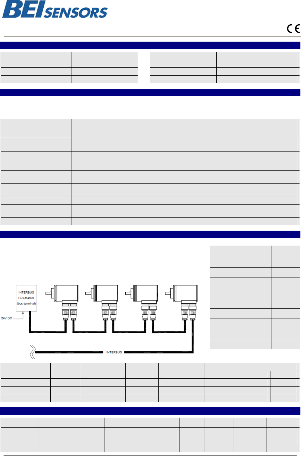
The rotary encoder is connected by two cables via 9-pin connectors, one as input line,
the other one as output line. Each cable contains both power supply and the bus lines.
To ensure the correct wiring, the input socket on the encoder has pins (male) whereas
the output socket has holes (female). The address of the encoder is derived from its
physical position in the network. The encoder is designed for a remote bus with up to 32
bits of I/O data. In the master (controller) the actual process values occupy one or two
word addresses for profile K1 or K2 and K3, respectively.
Web :
www.beisensors.com
Male
(IB-In)
Signal
Female
(IB-Out)
1 DO 1
2 DO / 2
3 DI 3
4
DI / 4
5 GND 5
6 PE 6
7 + 10-30Vdc 7
8 GND (0V) 8
9 NC 9
IB-coupling Class Max. Bits Progr. No of words ID-code
Binary Hex
Remote Bus K1 16 No 1 IN 0000 0001 0011 0110 0136
Remote Bus K2 32 No 2 IN 0000 0010 0011 0110 0236
Remote Bus K3 32 yes 2 IN + 2 OUT 0000 0010 0011 0111 0237
ORDERING REFERENCE Contact the factory for special versions, ex: electronics, special flanges, connections…)
MHM5 IB A1 B 12 13 S 06 0 PRI
Absolute multi
turn encoder
Interbus Version
Code :
Binary
Number of
turns
2
12
(4 096)
Resolution
(pos./turn)
2
13
(8 192)
Servo
Flange
Shat
diameter :
6mm
Without
mechanical
option
M23
Connection
Changes possible without further notice - Version 100301