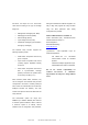
ABSOLUTE ROTARY ENCODER WITH CANOPEN INTERFACE USER MANUAL Main Features Programmable Parameters - Compact and heavy-duty industrial design - Direction of rotation (complement) - Interface: CANopen / CAN - Resolution per revolution - Housing: 58 mm - Total resolution - Solid/hollow shaft: 6 or 10mm / 15mm - Preset value - Max. 65536 steps per revolution (16 Bit) - Two limit switches and eight cams - Max.
Table of Contents General Security Advise......................................4 About this Manual................................................4 1. Introduction ......................................................5 1.1 General CANopen Information.........................5 2. Installation ........................................................7 2.1 Connection via Connection Cap.......................7 2.1.1 Signal Assignment ........................................7 2.1.
Object 2200h: Cyclic Timer PDO ......................... 40 Object 2300h: Save Parameter with Reset .......... 40 Object 3000h: Node Number ............................... 41 Object 3001h: Baudrate .......................................41 Object 3002h: Terminal Resistor.......................... 41 Object 3010h: Speed Control............................... 42 Object 3011h: Speed Value ................................. 42 Object 3020h: Acceleration Control .....................
General Security Advise Important Information This is the safety alert symbol. It is Read these instructions carefully, and look at the used to alert you to potential equipment to become familiar with the device personal injury hazards. Obey all before trying to install, operate, or maintain it. safety messages that follow this symbol to avoid The following special messages may appear possible injury or death.
After one turn the measuring range is completed 1. Introduction and starts again from the beginning. This manual explains how to install and Multi-Turn configure the OPTOCODE II absolute rotary Linear systems normally need more than one encoder with CANopen interface applicable for turn of a shaft. A single turn encoder is military and industrial applications with CANopen unsuitable for this type of application because of interface.
the device. It is unique on a bus. The function setting are available from different suppliers. It is code varies according to the type of message easy to align and program the rotary encoders being sent: using the EDS (electronic data sheet) configuration file provided.
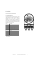
2. Installation 2.1 Connection via Connection Cap RT ON 2.1.1 Signal Assignment The rotary encoder is connected with two or three cables depending on whether the power supply is integrated into the bus cable or connected Ground + 24 V Supply voltage - 0 V Supply voltage G CAN Ground L CAN Low H CAN High G* CAN Ground x10 x1 Tab.
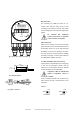
RT Bus Connection ON The connection cap fulfills the function of a Tcoupler. From there the wiring must be done according to the drawing on the left side. Please note the assignment of incoming and outgoing bus + - G L H G L H signals. An Bus In activated bus termination resistor will lead into a separation Bus Out of bus in and bus out signals! Cable Connection Remove screw, sealing and cone from the cable gland. Remove 55 mm of the sheath and 50 mm of the shielding.
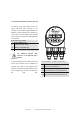
2.1.3 Setting Node Number in Connection Cap The setting of the node number is done by turning the BCD rotary switches in RT the ON connection cap. Possible (valid) addresses lie between 0 and 89 whereby every address can only be used once. Two LEDs on the backside of the connection cap show the operating status G L 78 L H 901 23 78 H G 901 23 456 456 456 Device address 0...89 23 BCD coded rotary switches x1 901 78 + of the encoder.
2.1.4 Setting Baudrate in Connection Cap The adjusting of the baudrate is adjusted by one Baudrate in kBit/s BCD coded rotary switches turn switch in the connection cap. The following 20 0 baudrates are possible: 50 1 100 2 125 3 250 4 500 5 800 6 1000 7 reserved 8 Sets SDO and LSS mode 9 Tab. 2 Baud rate Assignment Connection Cap 2.1.5 Status of the connection cap LEDs The LED behaviour was designed in accordance to the CiA normative DR 303-3 CANopen indicator specification.
CAN Run LED State Description Flickering AutoBitrate/ LSS The auto-bitrate detection is in progress or LSS services are in progress (alternately flickering with run LED)1 Blinking PREOPERATIONAL The device is in state PREOPERATIONAL Single flash STOPPED Double flash Triple flash The device is in state STOPPED Reserved for further use Program/ Firmware A software download is running on the device download On OPERATIONAL The device is in state OPERATIONAL Tab.
2.2 Installation of Connector and Cable encoders The new encoders with cable or connector exit fulfil all connection cap features, like: Node Number Addressing Baud Rate Setting Terminal Resistor 2.2.1 Signal Assignment The BEI Sensors absolute rotary with cable- and connector-exit were designed in accordance to CiA normative DR303-1 Cabeling and connector pin assignment.
2.2.2 Setting Node Number If the device has a connector, a cable exit or the node number span from 1 to 127 can be BCD-rotary-switch in the connection cap is set to addressed. The default node number is 32. To “9”, the node number has to be set via SDO set node number object 3000h has to be written. objects. An advantage of setting the node For further information regard chapter 5.5 Object number via software is, that the whole CANopen Dictionary.
Setting Baud Rate via LSS If the device has a connector, a cable exit or the Setting Services (LSS). The default baud rate is BCD-rotary-switch in the connection cap is set to 20 kBaud. For further information regard chapter “9”, the node number can be adjusted via Layer 4.5. 2.2.4 Switching the integrated Bus Terminal Resistor Object 3002h: Terminal Resistor This object allows the control of an internal terminal resistor. This resistor can be switched galvanically isolated via an a Photo-MOS-relay.
3. Technical Data In the following section you will find general with slightly different technical datas. For details technical datas for absolute rotary encoders with please refer to the corresponding datasheet of CANopen interface. There are several version the used encoder Electrical Data Interface Transceiver according ISO 11898, galvanically isolated by opto-couplers Transmission rate max.
Friction torque 3 Ncm (without shaft sealing) RPM (continuous operation) Singleturn: max. 12,000 RPM Multiturn: max. 6,000 RPM Shock (EN 60068-2-27) 100 g (half sine, 6 ms) Permanent shock (EN 60028-2-29) 10 g (half sine, 16 ms) Vibration (EN 60068-2-6) 10 g (10 Hz ...
4. Configuration The purpose of this chapter is to describe the configuration parameters of the absolute rotary encoder with CANopen interface. 4.1 Operating Modes 4.1.1 General The encoder accesses the CAN network after preoperational powerup in pre-operational mode: entails reduced activity on the network, which BootUp Message: 700 hex + Node Number simplifies the checking of the accuracy of the mode. Pre-operational mode sent/received SDOs.
4.1.4 Mode: Stopped To put one or all nodes in the stopped state, the master have to send the following message: Identifier Byte 0 Byte 1 Description 0h 02 h 00 NMT-Stop, all nodes 0h 02 h NN NMT-Stop, NN NN: node number It is possible to set all nodes (Index 0) or a single node (Index NN) to stop mode. 4.1.
4.3 Storing Parameter 4.3.
4.3.1 Storing Procedure The parameter settings can be stored in a non- by the parameter memory transfer. 2 volatile E PROM. The parameter settings are The stored parameters are copied stored in RAM when being programmed. When after a RESET (Power on, NMT- all the parameters are set and proved, they can 2 Reset) from the E PROM to the RAM (volatile 2 be transferred in one burn cycle to the E PROM memory).
Object 1018h: Identity Object (LSS-address) Subindex Description Data Type Default Value Access Restore after BootUp 0 Number of entries Unsigned 8 4 ro no 1 Vendor ID Unsigned 32 42h ro no 2 Product Code Unsigned 32 43h 41h ro no 3 Revision Number Unsigned 32 10000h ro no 4 Serial Number Unsigned 32 ro no Tab. 13: Identity Object The LSS master device requests services, that Table 10.
5. Programmable Parameters Objects are based on the CiA 406 DS V3.2: CANopen profile for encoders (www.can-cia.
The data transmission according to CAL is realized Index (hex) Object exclusively by object oriented data messages. The 0000 not used objects are classified in groups by an index record. 0001-001F Static Data Types Each index entry can be subdivided by sub-indices.
Identifier DLC NN 1 581 8 Command Index Download 6003h 43 03 Command Index Download 1010h 22 10 Subindex 60 Service/Process data Byte 4 Byte 5 Byte 6 Byte 7 00 00 10 00 00 Subindex Service/Process data Save Preset Values Identifier DLC NN 1 601 8 Version 07/10 10 01 Byte 4 Byte 5 Byte 6 Byte 7 73 61 76 65 BEI Sensors CANopen Manual serie M 24
5.2 Communication Profile DS301 specific objects from 1000h - 1FFFh In this manual we refer to the communication profile DS301 V4.
5.3 Manufacturer specific objects 2000h – 5FFFh Object Description Page Hand-Book 2000h Position Value 37 2100h Operating Parameters 37 2101h Resolution per Revolution 31 2102h Total Resolution 38 2103h Preset Value 39 2104h Limit Switch, min. 40 2105h Limit Switch, max.
6300h Cam state register 49 30 6301h Cam enable register 49 32 6302h Cam polarity register 49 33 6400h Area state register 52 6401h Work area low limit 53 6402h Work area high limit 53 6500h Operating status 53 63 6501h Single-turn resolution 54 64 6502h Number of distinguishable revolutions 54 65 6503h Alarms 54 65 6504h Supported alarms 55 66 6505h Warnings 55 67 6506h Supported warnings 56 68 6507h Profile and software version 56 69 6508h Operating ti
Object 1001h: Error Register This object is used by the device to display internal faults. When a fault is detected, the corresponding bit is therefore activated. The following errors are supported: Bit Description Comments 0 Generic Error The generic error is signaled at any error situation.
Subindex Description Data Type Default Value Access Restore after BootUp 0 - Unsigned 32 80000080h rw no Data Type Default Value Access Restore after Object 1008h: Manufacturer Device Name This object contains the device name. Subindex Description BootUp 0 - String - ro no Default Value Access Restore after Object 1009h: Manufacturer Hardware Version This object contains the article name of the circuit board.
Subindex Description Data Type Default Value Access Restore after BootUp 0 - Unsigned 16 0 rw yes Object 100Dh: Life Time Factor This object contains the life time factor parameters. The life time factor multiplied with the guard time gives the life time for the node guarding protocol.
0 Number of sub indices Unsigned 8 2 ro no 1 Restore all parameters Unsigned 32 “load” rw no Storing procedure To save the parameters to non volatile memory the access signature “load” has to be sent to the corresponding subindex of the device. Most significant word Least significant word ASCII D a o l Hex value 64h 61h 6Fh 6Ch Note: The restoration of parameters will only be taken into account after a power up or reset command.
Object 1016h: Consumer Heartbeat Time The consumer heartbeat time defines the expected heartbeat cycle time in ms. The device can only monitor one corresponding device. If the time is set to 0 the monitoring is not active. The value of this object must be higher than the corresponding time (object 1017) of the monitored device.
Object 1020h: Verify configuration This object indicates the downloaded configuration date and time. Subindex Description Data Type Default Value Access Restore after BootUp 0h Number of entries Unsigned 8 1h Configuration date 2h Configuration time 2h ro no Unsigned 32 rw no Unsigned 32 rw no Access Restore after Object 1029h: Error behaviour This object indicates the error behavior.
Subindex Description Data Type Default Value Access Restore after BootUp 0 Number of sub indices Unsigned 8 5 ro yes 1 COB-ID Unsigned 32 280h + Node ID rw yes 2 Transmission Mode Unsigned 8 1 rw yes 3 Inhibit Time Unsigned 32 0 rw yes 4 Not available 5 Event Timer Unsigned 32 0 rw yes Transmission Mode The transmission mode can be configured as described below: Transfer Value Transmission Mode Cyclic Acyclic (decimal) 0 1-240 241-251 Synchro Asynchr RTR nous on
16-bit field, the transmit PDO is always sent after the "event timer" expires. The value is written in subindex 5 of a transmit PDO. The data transfer also takes place with no change to data. The range is between 165536 ms. st Object 1A00h: 1 TPDO Mapping Parameter This object contains the mapping parameter of the 1st transmit PDO.
Object 1F51h: Program Control This is a special bootloader object, that has functionality for single turn encoders without connection cap only (see Bootloader chapter). This array controls the programs residing at index 0x1F50. Subindex Description Data Type Default Value Access Restore after BootUp 0h Number of program control Unsigned 8 entries 1h 2h Unsigned 32 ro yes rw yes Sub-index 1h and higher control the memory block functionality.
PDO with every change of the position value. Due to this, there will be generated a large amount of PDOs and a heavy bus load. Bit 0 Code Code Bit 1 sequence Limit switch, Bit 2 Limit min. max. switch, Bit 3 Event triggered PDO 0 CW increasing 0 off 0 off 0 off 1 CCW increasing 1 on 1 on 1 on Calculation Example: Target: Absolute rotary encoder with direction CCW decreasing, both limit switches disabled and event-triggered PDOs enabled.
This parameter is used to program the desired number of measuring units over the total measuring range. This value must not exceed the total resolution of the absolute rotary encoder, which is printed on the type sign of the encoder.
Object 2104h: Limit Switch, min. Two position values can be programmed as limit switches. By reaching this value, one bit of the 32 bit process value is set to high. Both programmed values must not exceed the parameter total resolution to avoid run-time errors. If the parameter value exceeds the total resolution of the encoder a SDO “Out of range” message is generated. Bit 30 = 1: Limit Switch, Min.
Status Function bits Bit Process value 31 30 29 28 27 26 25 24 23 22 21 20 19 18 17 16 15 14 13 12 11 10 9 8 7 6 5 4 3 2 1 0 1 0 X X X X X X X X X X X X X X X X X X X X X X X X X X X X X X Object 2160h: Customer storage This object provides for the customer the possibility to store any value. Attention: The values, written to these objects, will be stored in volatile memory, only.
0 Access code Unsigned 32 55AAAA55h wo no Object 3000h: Node Number This object contains the node number of the device. The BEI Sensors standard node number is 32. Subindex Description Data Type Default Value Access Restore after BootUp 0 Node Number Unsigned 8 1Fh rw Yes Access Restore after NOTE: To avoid the node number 0, one will be added to the value of this object! E.g.: 1Fh+1h = 20h = 32 (dec) Object 3001h: Baudrate This object contains the baudrate of the device.
Subindex Description Data Type Default Value Access Restore after BootUp 0 Terminal resistor BOOL 0h rw yes Object 3010h: Speed Control This object contains the speed control. The speed measurement is disabled by default.
0h Number of sub indices Unsigned 8 2h Ro 1h Enable Acceleration Unsigned 8 0h rw Yes 2h Acceleration modus Unsigned 8 0h rw yes Data Type Default Value Access Restore after Object 3021h: Acceleration Value This object contains acceleration value. Subindex Description BootUp 0h Acceleration Value INTEGER32 romap Acceleration-modus setting Delay [msec] Accuracy [steps/sec²] 0 40 +/-1’024 1 120 +/-512 2 750 +/-128 Tab.
Subindex Description Data Type Default Value Access Restore after BootUp 0h Bootloader Control Unsigned32 wo ATTENTION: Activating the boot loader courses a deep reset of the device. If the encoder enters boot loader mode, only a minimum object amount will remain, to assure basic communication. The device does not behave like an encoder anymore and waits for new programming. Firmware updates have to be done in close cooperation with the CAN product manager of BEI Sensors.
SFC: Scaling function (0 = disable, 1 = enable) CD: Commissioning diagnostic control (not availabe) CS: Code sequence (0 = CW, 1 = CCW) Code Sequence (CS Bit 0) is hardwired to Code Sequence (CS Bit 0) in object 2100h. Object 6001h: Measuring units per revolution This object shall indicate the number of distinguishable steps per revolution.
0h Process Value Unsigned 32 - romap yes Default Value Access Restore after Hardwired with Object 2000h. Object 6030h: Speed Value This object contains the speed value of the encoder. Subindex Description Data Type BootUp 0h Number of sub indices Unsigned 8 1h ro 1h Speed value channel1 Integer 16 - romap yes If the velocity exceeds the data type, the speed value is frozen to the maximal possible value. The customer can use the 3010h (32 bit) object.
5. The TPDO mapping Parameter 0 (1A01) has to be enabled, by setting the Number of entries (1A01Sub0) to 1, again: 601 8 22 01 1A 00 01 00 00 00 6. Finally the Speed has to be enabled by setting "Enable Speed" (3010Sub1): 601 8 22 10 30 01 01 00 00 00 7. To save this configuration please write 73 61 76 65 to 1010: 601 8 22 10 10 01 73 61 76 65 8.
Object 6200h: Cyclic timer This object contains the value of the event timer of the corresponding TPDOs. The value can be changed between 1-65538 ms. Subindex Description Data Type Default Value Access Restore after BootUp 0h Cyclic Time Unsigned 16 64h rw yes The object 6200h is hard-wired to the objects 1800h subindex 5h and 2200h and provide the cycle time for the cyclic mode.
BootUp 0h Number of sub indices Unsigned 8 1h ro 1h Cam polarity channel 1 Unsigned 8 0h rw yes List of Cam objects 6310h Cam1 low limit rw 0h VAR Highest sub-index supported 1h VAR Cam1 low limit channel1 rw Cam2 low limit rw 6311h U32 ro 0h VAR Highest sub-index supported 1h VAR Cam2 low limit channel1 rw Cam3 low limit rw 6312h U32 ro 0h VAR Highest sub-index supported 1h VAR Cam3 low limit channel1 rw Cam4 low limit rw 6313h U8 U8 VAR Highest sub-index su
1h VAR 6322h Cam2 high limit channel1 rw Cam3 high limit rw 0h VAR Highest sub-index supported 1h VAR Cam3 high limit channel1 rw Cam4 high limit rw 6323h U8 0h VAR Highest sub-index supported 1h VAR Cam4 high limit channel1 rw Cam5 high limit rw 6324h U8 ro ro 0h VAR Highest sub-index supported 1h VAR Cam5 high limit channel1 rw Cam6 high limit rw 6325h U8 VAR Highest sub-index supported 1h VAR Cam6 high limit channel1 rw Cam7 high limit rw VAR Highest sub
1h VAR 6336h Cam6 hyteresis channel1 rw Cam7 hyteresis rw 0h VAR Highest sub-index supported 1h VAR Cam7 hyteresis channel1 rw Cam8 hyteresis rw 6337h 0h VAR Highest sub-index supported 1h VAR Cam8 hyteresis channel1 U8 U8 ro 0x1 ro 0x1 rw Object 6400h: Area state register This object contains the area state register The object provides the actual area status of the encoder position. Figure 9 specifies the object structure and Table 106 specifies the value definition.
0 r Reserved Object 6401h: Work area low limit This object indicates the position value, at which bit 2 of the according work area state channel in object 6400h shall flag the underflow of the related work area. Subindex Description Data Type Default Value Access Restore after BootUp 0h Number of sub indices Integer 32 1h ro 1h Work area low limit channel 1 Integer 32 0h rw yes This object is hardwired with 2104h (Limit Switch Min).
Object 6501h: Single-turn resolution The object contains the physical measuring steps per revolution of the absolute rotary encoder. Subindex Description Data Type Default Value Access Restore after BootUp 0h Single Turn Resolution Unsigned 32 see type sign ro no Access Restore after Object 6502h: Number of distinguishable revolutions This object contains number of revolutions of the absolute rotary encoder.
Object 6504h: Supported alarms The object shall provide the supported alarms of the device. Please refer to the bit structure table to find more details about the supported alarms. Subindex Description Data Type Default Value Access Restore after BootUp 0h Supported Alarms Unsigned 16 1000h ro no The CA-encoder supports the position error alarm. Object 6505h: Warnings This object shall provide the warnings.
Object 6506h: Supported warnings The object provides the supported warnings of the device. Please refer to the bit structure table to find more details about the supported warnings. Subindex Description Data Type Default Value Access Restore after BootUp 0h Supported Warnings Unsigned 16 1000h ro no Currently there are not supported warnings available for an Optocode absolute rotary encoder. The CA-encoder supports the manufacture specific warning (Bit 12).
Object 6509h: Offset value This object contains the offset value. It is been calculated by the preset function and shifts the physical position value with the desired value. Subindex Description Data Type Default Value Access Restore after BootUp 0h Offset value Integer 32 - ro no Object 650Ah: Module identification This object shall provide the manufacturer-specific offset value, the manufacturer-specific minimum and maximum position value.
Check if all bus node has the same baud rate. If 6. Troubleshooting one node has another baud rate error frames are produced automatically. 6.1 Power on – Encoder doesn’t respond Problem: The bus is active but the installed encoder 6.4 Limit switches without function transmitted no boot up message. Problem: The encoder didn’t transmit the bits for the limit Possible solution: - switch of the PLC - remove the connection switches.
7.
Hollow shaft (B) 72 Ø63 Single-Turn = 90, Multi-Turn = 102 Single-Turn=100 , Multi-Turn=112 3,3 20 Ø60 63,5 Ø15 F7 23 20° Ø59 (Ø61)* 1,3 * Edelstahl / Stainless steel Max. W ** = 30 Min.
Connection cap AH58-B1CA-1BW, 5pin round connector M12, Micro style 20 66 23 Ø60 30 15 12 Connection cap AH58-B1CA-2BW, female and male connector 5pin connector M12, Micro Style 20 66 23 Ø60 30 15 12 Version 07/10 12 BEI Sensors CANopen Manual serie M 60
Synchroflange (S) Two versions available Synchroflange d / mm l / mm Cable exit (cable diameter = 8 mm ) Version S06 6f6 10 Version S10 10h8 20 Ø42 ~28 L 3xM4x6 Ø59 d Ø50f7 Ø58 ° 20 3x1 5 l ~33 3 3 4 ~18 25 L 30 Clampflange (C10) Single-Turn 53mm Cable exit (cable diameter = 8 mm ) Multi-Turn 62mm or 5 pin M12 connector ~28 L 3xM4x6 5 15° Ø59 Ø10 h8 Ø36 f7 Ø53 Ø58 1 18 Ø4 8 3x 1 2 0° 0° 12 3x 3xM3x6 3 ~33 3 25 ~18 30 Version 07/10 BEI Sensors CANopen M
Clampflange (C), 9 pin D-Sub connector Single-Turn=53, Multi-Turn=62 8 3xM4x6 Ø4 8 3x12 0° 15° 13 Ø59 1 UNC 4-40 Ø10 h8 Ø36 f7 Ø53 Ø58 0° 18 12 3x 3xM3x6 3 3 L Single-Turn 53mm Multi-Turn 62mm Synchroflange (S), 9 pin connector The dimensions of encoder housing in the versions cable exit, 12 pin circular connector and 5 pin connector from clamp flange are also valid for the synchro flange.
Blind shaft (B) Cable exit (cable diameter = 8 mm) or 5 pin M12 connector L Single-Turn 72mm Multi-Turn 81mm Mounting instructions The clamp ring should only be tightened if the (this reducing adapter can be pushed into the shaft of the driving element is inserted into the hollow shaft). hub shaft.
Heavy Duty version with solid shaft Clamp flange as well as synchro flange with 10mm shaft available 30 M4x6 Singleturn=45, Multiturn=69 3x 0 12 10 ° Ø48 Ø60 73 Ø36 f7 Ø10 h8 Ø58 1 18 12,5 32 21,5 IN OUT 55 Heavy Duty version with blind shaft Maximum shaft movements of drive element are listed in the table. Axial Radial static ± 0,3 mm ± 0,5 mm dynamic ± 0,1 mm ± 0,2 mm 72 Singleturn=66, Multiturn=90 Ø63 3,3 73 20 Ø60 20° Ø12 F7 1,3 Anlagekante an Momentenstütze Ø3.
Appendix A: Order Codes Description Type key Optocode MHM5-MHK5-MHO5 CA Interface CANopen CA Version A1 B- __ __ - _ __ _- ___ A1 Code Binary Revolutions (Bits) Singleturn 00 Multiturn (4096 revolutions) 12 Multiturn (16384 revolutions) 14 Steps per revolution Flange Shaft diameter Mechanical options B 4096 (0,09°) 12 8192 (0,04°) 13 65536 (0,005°) 16 Clamp flange C Synchro flange S Through Hollow Shaft T Blind shaft B 06 mm (MHM5) 06 10 mm (MHM5 10 12 mm (T
Connection caps All connections caps are equipped with a switchable terminal resistor, integrated T-coupler for CAN bus lines, BCD switches to adjust baudrate and node number, as well as LEDs for diagnosis. Description Aluminium housing with three M12 cable glands for cable diameters between 6,5 – 9 mm. Stainless steel housing with three M12 cable glands. Aluminium housing with one 5 pin male M12 connector.
Accessories and documentation Description Shaft Coupling Drilling: 10 mm / 10 mm Drilling: 6 mm / 6 mm Drilling: 4 mm – 11 mm Clamp Disc Set (4 pieces).
Appendix B: History and Compatibility History encoder generations 3.3 Object 1802h This chapter gives you information about older In types of absolute rotary encoder with CANopen parameterised by the object 1801h and 1802h. interface. Technical changes and compatibilities This is not consistent with the CiA standards and between the different types are specified. will be ended with the new encoder line.
no errors will occur. Merely the enhanced Singleturn 10196h Mutliturn 20196h functions, like velocity- and acceleration-output, will not be available. In case for unexpected problems, there is the possibility 3.
Version history connection cap Changes of the CANopen protocol In particular the design of the connection cap is The following changes have not be relevant to improved. Easier installation due to a new type you because only specific function according to of screw terminals inside of the connection cap. the newest CANopen specification (DS-301 On the back of the connection cap two multi- V4.0) are not supported anymore or are new color LEDs are implemented for easy diagnosis. implemented.
Polling in Pre-Operational state The old generation has Handling of spare parts accepted polling Boot-up message new encoder and old requests in pre-operational state, but wasn’t connection cap correct according to CANopen standard.
Beside the set up via hardware there is also the possibility to set up the protocol via SDO objects. For further information please refer the manual.
Appendix C: Glossary A Address Number, assigned to each node, irrespective of whether it is a master or slave. The encoder address (non-volatile) is configured in the base with rotary switches or SDO objects. APV Absolute Position Value. B Baud rate Transmission speed formulated in number of bits per second. Bus node Device that can send and/or receive or amplify data by means of the bus. Byte 8-bit unit of data = 1 byte. C CAL CAN application layer.
F FAQ FC Function code. Frequently Asked Questions Determines the type of message sent via the CAN network. L Line terminator LMT Resistor terminating the main segments of the bus. Network management object. This is used to configure the parameters of each layer in the CAN. Master "Active" device within the network, that can send data without having received a request. It controls data exchange and communication management. N NMT Network management object.
SDO Communication object, with a low priority for messaging (configuration, error handling, diagnostics). Slave Bus node that sends data at the request of the master. The encoders are always slaves. W WO Write Only: Parameter that is only accessible in write mode.
Appendix D: List of tables Tab. 1 Signal Assignment Connection Cap ..................................................................................................7 Tab. 2 Baud rate Assignment Connection Cap ...........................................................................................10 Tab.3: CAN Run LED states .......................................................................................................................11 Tab.4: CAN Error LED states.................................
2.2 21.05.04 New inner diameter of the cable glances 2.3 24.09.04 SubIndex of RestoreAllParameter changed 11/07 19.11.07 Complete Review of the manual 03/08 30.03.08 Complete Review, due to CA00 introduction 07/09 28.07.