
User guide
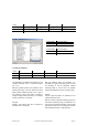

6.2 Supported diagnostic messages
In the following the different diagnostic messages
are described in detail.
6.2.1 Extended diagnostics header
B
yte 7 contains the length of the extended
diagnostics (including header itself).
6.2.2 Memory error
Bit 4 in diag
nostic byte 8 is used to indicate a
memory error.
Memory error means that the internal EEPROM of
the encoder no longer works correctly and that it
cannot be guaranteed that values (e.g. offset
value) are stored non-volatile.
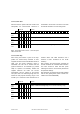
Bit Definition 0 1
4 Memory error
(defective EEPROM)
No Yes
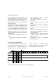
6.2.3 Operating status
Diagnostic byte 9 contains certain parameters (set
in the system configuration).
Bit Definition 0 1
0 Direction of rotation CW CCW
1 Class 2 functionality Off On
2 Diagnostic routine Off On
3 Scaling function Off On
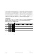
6.2.4 Encoder type
Diagnostic byte 10 contains the encoder version
(singleturn or multiturn).
Byte 10 Definition
0 Singleturn encoder
1 Multiturn encoder
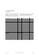
6.2.5 Singleturn resolution
Diagnostic bytes 11-14 contain the real (physical)
resolution per revolution of the encoder.
6.2.6 Number of revolutions
Diag
nostic bytes 15 and 16 contain the real
(physical) number of revolutions of the encoder.
Standard values are 1 for singeturn and 4096
(resp. 16384) for multiturn devices.
6.2.7 Operating time warning
Bit 4 in diag
nostic byte 21 indicates an operating
time warning. The bit is set after 10
5
hours.
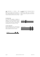
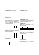
6.2.8 Profile version
Diagnostic bytes 24 and 25 contain the profile
version of the encoder.
Byte 24 25
Bit 15 – 8 7 – 0
Data 2
7
- 2
0
2
7
- 2
0
Revision No. Index
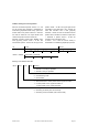
6.2.9 Software version
Diagnostic bytes 26 and 27 contain the software
version of the encoder.
Octet 26 27
Bit 15 – 8 7 - 0
Data 2
7
to 2
0
2
7
to 2
0
Revision No. Index
6.2.10 Operating time
T
he operating time of the encoder can be read out
from diagnostic bytes 28 to 31. If the encoder is
connected to the power supply the operating time
is stored in an EEPROM every six minutes in 0.1 h
steps.
Page 28 BEI Sensors Profibus Manual serie M Revision 03/10