
Manual

MHK5
BEI Sensors SAS
Tél : +33 (0)3 88 20 80 80
Fax : +33 (0)3 88 20 87 87
Mail : info@beisensors.com
Espace Européen de l’Entreprise
9, rue de Copenhague
B.P. 70044 Schiltigheim
Web :
www.beisensors.com
F
67013 Strasbourg Cedex
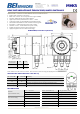
DEVICE NET ABSOLUTE MULTI-TURN ENCODER, MHK515-DNET RANGE
ELECTRICAL DATA
Interface Transceiver according ISO/DIS 11898 Power consumption max 2,5W
Transmission rate Max 500KBauds Step frequency LSB 800 kHz
Device addressing By rotary switches
Accuracy of division
+ ½ LSB
Power Supply 10 – 30Vdc EMC EN 61000-6-4 EN 61000-6-2
Current consumption max. 100mA (24Vdc) Electrical lifetime > 10
5
h
TRANSMISSION MODE
Polled Mode
By a telegram the connected host calls for the current process value. The absolute rotary encoder reads
the current position value, calculates eventually set-parameters and sends back the obtained process
value by the same identifier
Change of State
The absolute rotary encoder transmits the actual process value. The process value is transmitted when the
position changes. This is useful to reduce the bus activity
CYCLIC Mode
The absolute rotary encoder transmits the actual process value event controlled by an internal timer. This
is also useful to reduce the bus activity
PROGRAMMABLES PARAMETRES
Operating Parameters
As operating parameters the code sequence (complement) can be programmed. This parameter
determines the counting direction, in which the output code increases or decreases
Resolution (pos./turn)
The parameter resolution per revolution is used to program the desired number of steps per revolution.
Value between 1 and 8 192 can be programmed
Total Resolution
“Max-RANGE“
This parameter is used to program the desired number of measuring units over the total measuring range.
This value may not exceed the total resolution of the absolute rotary encoder. If the encoder is used in a
continuous measuring application, certain rules for the setting of this parameter must be followed. These
rules are outlined in the manual
Preset Value
The preset value is the desired position value, which should be reached at a certain physical position of
the axis. The position value is set to the desired process value by the parameter pre-set
INSTALLATION
The rotary encoder is connected by three cables. The power supply is achieved with a two-wire
connection cable through one PG 9. Each one of the twisted-pair and shielded bus lines are guided in
and out through two PG 9 on the right side (as seen on clamps)
CONFIGURATION
The setting of the node number is achieved by 2 turn-switches in the connection cap. Possible
addresses lie between 0 and 63 whereby every address can only be used once. 2 LEDs on the
backside of the connection cap show the operating status of the encoder
There is a resistor provided in the connection cap, which must be used as a line termination on the last
device
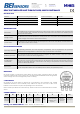
ORDERING REFERNCE
(Contact the factory for special versions, ex: electronics, special flanges, connections…)
MHK5 D2 B1 B 12 13 B 15 0 0CC
Absolute
multi turn
encoder
DEVICE
NET
Version
Code :
Binary
Number of
turns
2
12
(4 096)
Resolution
(steps/turn) :
2
13
(8 192)
Blind
Shaft
Shaft diameter
(reduction ring
available upon
request)
Without
mechanical
options
Connection
Cap output
Ordering code: MHK515-DNET-001 = MHK5 - D2 B1 B – 12 13 - B15 0 - 0CC
Changes possible without further notice - Version 2.0