
Owner's manual

IHK5
BEI Sensors SAS
Espace Européen de l’Entreprise
9, rue de Copenhague
B.P. 70044 Schiltigheim
F 67013 Strasbourg Cedex
Tél : +33 (0)3 88 20 80 80
Fax : +33 (0)3 88 20 87 87
Mail : info@beisensors.com
Web :
www.beisensors.com
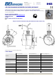
ATEX PROGRAMMABLE INCREMENTAL ENCODERS, IHK5 RANGE
OUTPUT ELECTRONIC / SUPPLY - DIGITAL SIGNALS (SQUARE WAVE SIGNALS) - 2P2 ELECTRONIC
Supply : 4.5 to 6Vdc, Consumption : 75mA
Intern capacity : 1.3µF, intern inductance : 0mH
RS422, 40 mA, TTL 20mA, F
max
= 300kHz
II 1 G/D EEx ia IIC T4, Ex iaD 20 T135°C
Barrier to be used for supply:
Ui≤10V, Li≤750mA, Pi≤1.875W
Barrier to be used for each output:
Ui≤10V, Li≤200mA, Pi≤0.5W
Protection against short circuits
STANDARD CONNECTION
- + A B 0 A/ B/ 0/ Ground
G6 12 pins CW 1 2 3 4 5 6 7 8
Body
Connector
G8 12 pins CCW 10 + 11 2 + 12 8 5 3 1 6 4
Body
Connector
G3
PVC cable 8
wires 8230/020
WH
white
BN
brown
GN
green
YE
yellow
GY
grey
PK
pink
BU
blue
RD
red
General
Shielding
GP
PUR cable 12
wires 8230/050
WH white +
WH/GN white / green
BU blue +
BN/GN brown / green
GY
grey
BN
brown
RD
red
PK
pink
GN
green
BK
black
General
Shielding
ORDERING REFERENCE
Shaft Supply Output stage Signals Resolution Connection
Orientation
G6 :M23 12pins CW
G5 :M23 12pins CW
G8 : M23 12 pins CCW
G1 : solenoid 4 pins
G2 : DIN 5 pins
GD : DIN 8 pins
R : radial
IHK5
Cover :
Zinc alloy
Body :
Aluminium
14 : 14 mm 2 : 5Vdc
P2 : driver
RS422
9 : A,A/,B,B/,0,0/
(0, gated A&B)
Basic:
5 000
max
G3 : PVC cable 8 wires
GP : PUR cable 12 wires
Example :
R020: radial
cable 2m
Ex: IHK5 _ 14 // 2 P2 9 //
5 000 //
GP R050
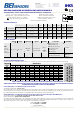
AVAILABLE INTERPOLATED RESOLUTIONS
Simple multiplication of the basic disk resolution : 1, 2, 3, 4, 5, 8, 10, 12 and 16 times by dip-switch without software, nor hardware
Basis Resolutions
Interpolation
Factor
250 256 360 500 1 024 2 500 3 000 3 600 4 000 4 096 5 000
X 1
250 256 360 500 1 024 2 500 3 000 3 600 4 000 4 096 5 000
X 2
500 512 720 1 000 2 048 5 000 6 000 7 200 8 000 8 192 10 000
X 3
750 768 1 080 1 500 3 072 7 500 9 000 10 800 12 000 12 288 15 000
X 4
1 000 1 024 1 440 2 000 4 096 10 000 12 000 14 400 16 000 16 384 20 000
X 5
1 250 1 280 1 800 2 500 5 120 12 500 15 000 18 000 20 000 20 480 25 000
X 8
2 000 2 048 2 880 4 000 8 192 20 000 24 000 28 800 32 000 32 768 40 000
X 10
2 500 2 560 3 600 5 000 10 240 25 000 30 000 36 000 40 000 40 960 50 000
X 12
3 000 3 072 4 320 6 000 12 288 30 000 36 000 43 200 48 000 49 152 60 000
X 16
4 000 4 096 5 760 8 000 16 384 40 000 48 000 57 600 64 000 65 536 80 000
NEVER CONNECT/DISCONNECT OR OPEN THE ENCODER UNDER POWER SUPPLY IN DUST ENVIRONMENTS
RESPECT THE MOUNTING TOLERANCES AND THE MECHANICAL RESTRICTIONS IN ORDER TO REMAIN IN LINE WITH THE MAXIMAL SURFACE
TEMPERATURE VALUE ALLOWED BY THE CLASS T4 REQUIREMENTS
LCIE 04 ATEX 6109 X : CE certification of Type for the encoder :
Operating temperature : -30°C to +70°C
The components of the device are intrinsically safe : they can be used in explosive atmospheres. The supply and outpu circuits can
only be connected to associated devices which are intrinsically safe and that are certified by type (ia) or (ib). These devices must
have electrical parameters that have a compatible supply with the above mentioned eletronics
LCIE 04 ATEX 6155 X : CE certification of Type for the encoder’s system (encoder in association with a BEI barrier) :
Operating temperature : barrier -20°C to +40°C and encoder -30°C to +70°C
System classification : EEx ia IIC T4 Ex iaD 20 T135°C
The interconnecting cables have to be sufficiently protected against damage and have to be separated from the non intrinsically
safe circuits. They are described in the norm EN50020 paragraph 6.3, with the following characteristics C=100pF/m and L=1.2µH/m, or
with cables with other C and L values, with respect to the maximum authorized :
Gases : Ca=3.9µF and L=0.4mH
Dust : Ca=38.7µF and L=0.8mH
Made in FRANCE
Changes possible without further notice - Version 080919