Version 1.2 June 2001 ® www.behringer.
ULTRA-CURVE PRO DSP8024 SAFETY INSTRUCTIONS CAUTION: To reduce the risk of electric shock, do not remove the cover (or back). No user serviceable parts inside; refer servicing to qualified personnel. WARNING: To reduce the risk of fire or electric shock, do not expose this appliance to rain or moisture. This symbol, wherever it appears, alerts you to the presence of uninsulated dangerous voltage inside the enclosure—voltage that may be sufficient to constitute a risk of shock.
ULTRA-CURVE PRO DSP8024 FOREWORD Dear Customer, welcome to the team of ULTRA-CURVE PRO users and thank you very much for expressing your confidence in BEHRINGER products by purchasing this unit. It is one of my most pleasant tasks to write this letter to you, because it is the culmination of many months of hard work delivered by our engineering team to reach a very ambitious goal: making an outstanding device better still.
ULTRA-CURVE PRO DSP8024 ULTRA-CURVE PRO Ultra-high performance digital stereo mainframe powered by two 24-bit high-speed digital signal processors DSP8024 s High-end AKM and CRYSTAL 24-bit AD/DA converters for ultra-high dynamic range and resolution s Open-ended & “future-proof” architecture allows for future software upgrades s Ultra-musical dual 31-band graphic equalizer with “true frequency response” characteristics s Low/high/bell shelving tool with variable slope (3 - 30 dB) s Real time analyzer
ULTRA-CURVE PRO DSP8024 TABLE OF CONTENTS 1. INTRODUCTION..................................................................................................................... 6 1.1 The design concept ......................................................................................................................... 6 1.2 Before you begin ............................................................................................................................. 6 1.3 Control elements .................
ULTRA-CURVE PRO DSP8024 1. INTRODUCTION The BEHRINGER ULTRA-CURVE PRO is a fully digital sound processing device based on DSPs and 24-bit A/D and D/A converters. The high-speed DSPs are capable of performing any process in fractions of a second, the only element governing their performance being the software. The enormous flexibility available means that the ULTRA-CURVE PRO has a range of features greatly exceeding those found in a conventional analog graphic equalizer—at a price previously unimaginable.
ULTRA-CURVE PRO DSP8024 The automatic servo function recognizes the presence of unbalanced connectors and adjusts the nominal level internally to avoid level differences between the input and output signals (6 dB correction). The optional digital input and output (AES/EBU interface) connections are balanced with a negative ground. High-quality connectors ensure isolated, noise-free signal throughput. The MIDI connections (IN/OUT/THRU) have been realized with standardized DIN plug-in connectors.
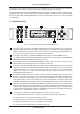
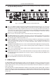
ULTRA-CURVE PRO DSP8024 + In each case pressing on the opposite key while holding the key being used will accelerate the operation being carried out. Fig. 1.2: The rear panel layout of the ULTRA-CURVE PRO 9 This is the MAINS CONNECTOR/FUSE HOLDER/VOLTAGE SELECTOR. Before you connect the unit, please make sure that the displayed voltage corresponds to your mains supply. Please note that, depending on the mains voltage supplied to the unit, the correct fuse type and rate must be installed.
ULTRA-CURVE PRO DSP8024 2.1 EQ mode Fig. 2.1: Main EQ window of the ULTRA-CURVE PRO The display shows a 31-band graphic equalizer, along with the main fader for overall level control—slightly separated on the right hand side. On the left are the pictograms for the softkeys, which are used to open the sub-menus. 2.1.1 Operating the graphic equalizer The selected controller is illustrated highlighted in the display.
ULTRA-CURVE PRO DSP8024 When the limiter threshold is exceeded, the indication LIM will appear in the level meter display to indicate that the limiter is attenuating the output. With softkey A you leave the level meter, and return to the main EQ window. With softkey B you erase the maximum levels from the memory. With softkey C / you switch the display from the ULTRA-CURVE PRO input and output. With key D you can choose between three different tables of reference levels.
ULTRA-CURVE PRO DSP8024 search means that the audio signal is continuously examined for signs of feedback. If feedback is detected, the ULTRA-CURVE PRO will assign an appropriate filter to the relevant frequency and apply narrow band attenuation, also known as a “notch filter”. The parameters which have been used will be continuously displayed. The next feedback will be dealt with by the next available filter.
ULTRA-CURVE PRO DSP8024 question “CLEAR PROGRAM IN MEMORY?” which can be confirmed with at this point and leave the settings as they are. . By using you can stop We recommend that you make use of this feature whenever you have something completely new to do and have to start from scratch. This way, you can carry on without the danger that maybe an old feedback destroyer setting is in the place which could cause problems.
ULTRA-CURVE PRO DSP8024 Channel switching In the EDIT menu, you can switch back and forth between the two channels, using softkey C. The pictogram for softkey C will show you which channel is active, and whether or not the channels are connected to each other via the stereolink function: left channel, stereolink on right channel, stereolink on left channel, stereolink off right channel, stereolink off.
ULTRA-CURVE PRO DSP8024 possibly causing the noises mentioned above. SHELVING SLOPE This is a tool which you can use to easily add high shelving, low shelving and bell-shaped response curves to the graphic equalizer (see section 2.1.5 on previous page). LIMIT THRESHOLD The ULTRA-CURVE PRO has an integrated digital limiter to protect against overloading and resulting distortion. Its Attack Time is zero, in other words, it reacts “in advance”.
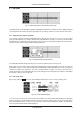
ULTRA-CURVE PRO DSP8024 f: the frequency in Hertz of the selected band, act: the level present as the display was frozen, max: the highest level reached on this frequency up to the point in time when the display was frozen (the maximum values stored in memory can be replaced). + The levels displayed in the RTA refer to the digital maximum. PROGRAM: Shows the current RTA program number (1-10). In contrast to EQ programs, it is not possible to name RTA programs. If after approx.
ULTRA-CURVE PRO DSP8024 increasing the decay results in a slower display. + Short decays are necessary to display fast processes, whereas using long decays with static signals will result in a “quieter” display, which is usually desirable for this type of signal. 2.2.5 RTA setup The RTA SETUP menu is opened by pressing the SETUP key. The RTA SETUP window appears in the display and the LED above the SETUP key flashes. Fig. 2.
ULTRA-CURVE PRO DSP8024 = sine wave, OFF = signal generator off or INPUT = input signal. White noise is composed of multitudes of sine waves packed close together, of equal amplitude, whose phases are random compared to each other (statistically different from each other). Their “density” or, spectral intensity is constant at any given frequency. With pink noise, the spectral intensity is inversely proportional to the frequency.
ULTRA-CURVE PRO DSP8024 more than 12 dB to reach the desired frequency response. If this is the case, you may assume that the loudspeaker system being used is not capable of reproducing this frequency (typically if it is a very low or high frequency). The ULTRA-CURVE PRO will therefore completely avoid the boosting of this frequency to any extent. This will avoid any overloading of the loudspeakers. Please bear in mind that the test signal passes through the equalizer during the measurement procedure.
ULTRA-CURVE PRO DSP8024 rates, the ULTRA-CURVE PRO will be muted for approx. 1 sec., as all the filter parameters have to be recalculated. In purely analog mode the 48 kHz rate should be used. Apart from the fact that the high sample rate gives the widest frequency response and correspondingly the best possible sound, at this rate the fastest signal processing takes place. VIEWING ANGLE Viewing angle controls the contrast adjustment for the display, in increments from 0 to 31.
ULTRA-CURVE PRO DSP8024 MIDI Here the MIDI function is switched on or off. Toggle between ON and OFF with the +/- buttons. CHANNEL This field indicates the current MIDI channel. OMNI MODE signifies that MIDI commands from all channels are received. SND MEMORY DUMP You can send a MIDI dump using the +/- buttons. The complete memory will be transferred and can be stored externally. RCV MEMORY DUMP You can start the reception of a MIDI dump using the +/- buttons. The externally saved data can be reloaded.
ULTRA-CURVE PRO DSP8024 To obtain the best results the following points should be paid close attention to: Experience has shown that, before beginning to use the equalizer, it is sensible to listen to a variety of music and speech material with which you are thoroughly familiar, playing these references “straight” through the system without any corrective EQ.
ULTRA-CURVE PRO DSP8024 Positions 1 and 2 are about three feet directly in front of the loudspeaker system, positioned halfway between the middle and high frequency components. These measurements can be used as a control of the basic system functions. Position 3 is about seven feet in front of the stage centre. Measurements taken here should show an identical response above 250 Hz as obtained from positions 1 and 2.
ULTRA-CURVE PRO DSP8024 musicians—their hearing will recover sensitivity during a pause—the end result is that you recover valuable headroom. If you are repeatedly using the same monitor loudspeakers, you can save the EQ settings which you have set for these speakers (store them under names such as wedge 15" or drumfill). Extremely low frequencies should be filtered out to avoid a “muddy” stage sound. + Set the shelving tool to give you a high pass filter.
ULTRA-CURVE PRO DSP8024 the stage the same clear, direct sound as those with better positions. In order to compensate for the time differences existing between the main L and R loudspeakers and those further away, the signal to the latter will be sent through an electronic delay device. This usually is a separate line-delay unit designated solely for this purpose. The ULTRA-CURVE PRO removes the necessity of a separate delay unit, as it can produce a signal delay for the material it is processing.
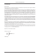
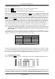
ULTRA-CURVE PRO DSP8024 4. “TRUE RESPONSE” CHARACTERISTIC The BEHRINGER ULTRA-CURVE PRO differs greatly from conventional graphic equalizers, in its filter concept and resulting method of operation. Conventional graphic equalizers are, by the physical nature of their design, subject to strong interaction between adjacent filters, resulting in a difference between the frequency curve suggested by the fader position, and the real frequency curve achieved.
ULTRA-CURVE PRO DSP8024 Fig. 4.2: ULTRA-CURVE PRO with “true response” Fig. 4.3: Combination of 4.1 and 4.2—with the fader positions added 5. ULTRA-CURVE PRO STRUCTURE 5.1 Hardware The analog input signals first pass through the electronic balancing amplifier and are then fed to the A/D converters. Here they are converted into a time division multiplex digital signal suitable for the DSPs. The reference microphone input feeds a balanced amplifier, which raises the signal level by 20 dB.
ULTRA-CURVE PRO DSP8024 to one of the A/D converter inputs. Switching onto a particular input can be carried out in the RTA or RTA SETUP menu. The digital input signal goes straight through the transformer balanced input directly to the DSPs (applicable only when the AES/EBU option is installed). Switching between the analog and digital input sources is done in the SETUP menu. Signal processing is accomplished by the two DSPs.
ULTRA-CURVE PRO DSP8024 At first, the level will be determined before processing. This information is sent to and displayed by the level meter. Apart from this the input signal will be delayed if a delay time is set. Once again, a level will be determined, this time from the delayed signal. This will be used to control the noise gate. At the same time, the overall level (master volume) will be set. This is done prior to processing, so that the processing filters in the signal path will not be overloaded.
ULTRA-CURVE PRO DSP8024 6. INSTALLATION 6.1 Mains connection Before you switch on the unit, check that it is configured to match your AC mains voltage requirements. If it does not comply, then it is necessary to switch the operating voltage to the correct supply requirements before turning on the unit, otherwise the unit could be severely damaged. You will find this combined fuse holder/ voltage selector at the back, adjacent to the IEC receptacle.
ULTRA-CURVE PRO DSP8024 Unbalanced use of mono 1/4" jack plugs Balanced use of stereo 1/4" jack plugs Tip = Signal Tip = hot (+ve) Ring = cold (-ve) Sleeve = Ground / Shield Sleeve = Ground / Shield Tip Tip Sleeve Ring Sleeve Strain relief clamp Strain relief clamp For connection of balanced and unbalanced plugs, ring and sleeve have to be bridged at the stereo plug.
ULTRA-CURVE PRO DSP8024 Fig. 6.2: Adaptor S/PDIF out > ULTRA-CURVE PRO AES/EBU in Connecting from the ULTRA-CURVE PRO AES/EBU output to an S/PDIF input will probably not work, because the copy prohibit function present at the S/PDIF device will be triggered by a channel status bit, or possibly another AES/EBU defined bit, preventing data transfer. 6.
ULTRA-CURVE PRO DSP8024 ULTRA-CURVE PRO is switched off. If you decide to replace the battery yourself please note that you will invalidate your warranty. + + + Disconnect the ULTRA-CURVE PRO from mains before opening the enclosure. Warning: Danger of explosion when battery is placed incorrectly! Replace only with the same type (see technical specifications). When replacing the battery, the correct polarity should be observed. Empty batteries are toxic waste and must be disposed of properly. 7.
ULTRA-CURVE PRO DSP8024 Status Bytes Program Changes Pcxx c = Channel xx = Program (0..99) Controller Offset adjustable from 0 to 64 * Ccxx c = Channel xx = Number Controller Data Bytes Contrl. Number Parameter Definition Range 0-30 31 32-62 63 EQ Left Master Level Left EQ Right Master Level Right 20 Hz, 25 Hz, ..., 16 kHz, 20 kHz 0 - 127 0 - 127 0 - 127 0 - 127 20 Hz, 25 Hz, ..., 16 kHz, 20 kHz Tab. 7.2: MIDI controller * You can adjust an offset for the MIDI controller.
ULTRA-CURVE PRO DSP8024 8. TECHNICAL SPECIFICATIONS Analog audio inputs Connectors XLR and 1/4" TRS connectors Type servo-balanced input with RF rejection Impedance 50 kOhm balanced, 25 kOhm unbalanced Max. input Level +21 dBu balanced and unbalanced CMRR typical 40 dB, >55 dB @ 1 kHz Analog audio outputs Connectors XLR and 1/4" TRS connectors Type DC-decoupled, servo-balanced output stage Impedance 60 Ohm balanced, 30 Ohm unbalanced Max.
ULTRA-CURVE PRO DSP8024 Digital delay Type Maximum delay time Minimum resolution Delay unit Level meter Type Attack/Decay (RMS) Attack (Peak) Decay (Peak) Noise gate Type Threshold Attack/Release Limiter Type Threshold Release Real time analyzer (RTA) Type Frequency range Detectors Decay Sine wave generator Noise generator Display Type Backlight Contras Memory EQ programs RTA measurements Password protection Power supply Operating voltage Power consumption Fuse rating Mains connection Battery Battery life
ULTRA-CURVE PRO DSP8024 9. WARRANTY § 1 WARRANTY CARD/ONLINE REGISTRATION To be protected by the extended warranty, the buyer must complete and return the enclosed warranty card within 14 days of the date of purchase to BEHRINGER Spezielle Studiotechnik GmbH, in accordance with the conditions stipulated in § 3. Failure to return the card in due time (date as per postmark) will void any extended warranty claims.