
Manual


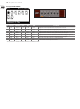
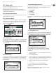
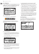
Table Of Contents
- Thank you
- Important Safety Instructions
- Legal Disclaimer
- Limited warranty
- About the DeepMind 12
- 1. Introduction
- 2. Features
- 3. Controls
- 4. Program Management
- 5. Playing Guide
- 6. Signal Path / Voice Structure
- 7. Menu System
- 8. Programming
- 9. Effects Reference Guide
- 10. Short-cuts
- 11. Applications
- 12. DAW MIDI Configuration
- 13. System Block Diagram
- 14. Connection Wiring Diagrams
- 15. Technical Specifications
- 16. MIDI Commands
- 17. MIDI NRPN Commands
- 18. Global Commands
- 19. MIDI SysEx Commands
- 20. Firmware Update
- 21. Troubleshooting
- 22. Bootloader Menu
- 23. Definition of Terms
- 24. Appendix 1 - Octave Shifting
- 25. Appendix 2 - ARP/SEQ/LFO Sync Timing
- 26. Appendix 3 - Poly Chords
- 27. Appendix 4 - Default Program
- 28. Appendix 5 - Revert to Panel

115 DeepMind 12 User Manual
Chorus-D (DIMENSIONAL CHORUS)
No DM12 REF PARAMETER UNITS MIN MAX DESCRIPTION
1 ON On — OFF ON Allows the eect to be turned On or O.
2 MOD Mode — M ST Switches the operation between Mono and Stereo modes.
3* MIX Mix % 0.0% 100% Controls the mix (or ratio) of wet (processed) and dry (unprocessed) signals.
4 SW1 Sw1 — OFF ON Engages level one intensity (minimum).
5 SW2 Sw2 — OFF ON Engages level two intensity.
6 SW3 Sw3 — OFF ON Engages level three intensity.
7 SW4 Sw4 — OFF ON Engages level four intensity (maximum).
* These parameters are available as modulation destinations in the Modulation Matrix
Flanger (STEREO FLANGER)
No DM12 REF PARAMETER UNITS MIN MAX DESCRIPTION
1* SPD Speed Hz
0.0 Hz
5 Hz Sets the modulation speed. Time synchronised options from 4 to 1/64 bars.
2* WDL WidthL %
0.0% 100%
Determines the amount of modulated delay in the left channel.
3* WDR WidthR % 0.0% 100% Determines the amount of modulated delay in the right channel.
4 DLL DelayL ms 0.5 ms 20.0 ms Sets the total amount of delay for the left channel.
5 DLR DelayR ms
0.5 ms 20.0 ms
Sets the total amount of delay for the right channel.
6* MIX Mix % 0.0% 100% Controls the mix (or ratio) of wet (processed) and dry (unprocessed) signals.
7* LC LoCut Hz 10.0 Hz 500.0 Hz Allows the low frequencies in the signal to be reduced.
8* HC Hi Cut Hz
200.0 Hz 20000.0 Hz
Allows the high frequencies in the signal to be reduced.
9 PHS Phase — 0.0 180.0 Adjusts the phase oset of the LFO between left and right channel.
10* FLC FeedLC Hz 10.0 Hz 500.0 Hz Adjusts the low cut lter frequency in the feedback path.
11* FHC FeedHC Hz
200.0 Hz 20000.0 Hz
Adjusts the high cut lter frequency in the feedback path.
12* FD Feed % -90.0% 90.0% Controls the percentage of positive or negative feedback.
* These parameters are available as modulation destinations in the Modulation Matrix