B-CONTROL FADER BCF2000 B-CONTROL ROTARY BCR2000 Version 1.
B-CONTROL FADER BCF2000/B-CONTROL ROTARY BCR2000 IMPORTANT SAFETY PRECAUTIONS IMPORTANT SAFETY INSTRUCTIONS: 1) Read these instructions. 2) Keep these instructions. 3) Heed all warnings. 4) Follow all instructions. CAUTION: To reduce the risk of electric shock, do not remove the cover (or back). No user-serviceable parts inside; refer servicing to qualified personnel. Only qualified personnel may perform repairs. 5) Do not use this apparatus near water. 6) Clean only with dry cloth.
B-CONTROL FADER BCF2000/B-CONTROL ROTARY BCR2000 FOREWORD Dear Customer, welcome to the team of BEHRINGER users, and thank you very much for expressing your confidence in us by purchasing the B-CONTROL. Writing this foreword for you gives me great pleasure, because it represents the culmination of many months of hard work delivered by our engineering team to achieve a very ambitious goal: to present two outstanding USB MIDI CONTROLLERS.
B-CONTROL FADER BCF2000/B-CONTROL ROTARY BCR2000 1.2 System requirements 1. INTRODUCTION Thank you very much for expressing your confidence in BEHRINGER products by purchasing the B-CONTROL. The B-CONTROL is an extremely flexible control surface suitable for a wide array of applications.
B-CONTROL FADER BCF2000/B-CONTROL ROTARY BCR2000 s set filter frequency to CC 05 s set filter resonance to CC 06 (receive) s set volume to CC 07 (receive) 2.2 The MIDI standard To get detailed information on how to assign them, please refer to chapter 4.3.2 Programming in the EDIT mode on page 13. Now, define in the B-CONTROL the control elements that will control these 3 parameters.
B-CONTROL FADER BCF2000/B-CONTROL ROTARY BCR2000 Control Change (CC): Control Change Messages are some of the most powerful MIDI messages. Using them, a vast number of parameters and functions can be recalled and automated. Individual control elements (faders, rotary dials, keys etc.) can be assigned to CC messages on your B-CONTROL. Because not only keys but also faders and rotary dials can be used, control values can be controlled in real time either statically or dynamically.
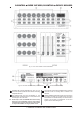
B-CONTROL FADER BCF2000/B-CONTROL ROTARY BCR2000 Fig. 3.1: The control surface of the B-CONTROLs Fig.3.2: The back of the BCF2000 (control elements + to coincide with the BCR2000) CONTROLLER connector (BCF2000 only). Here, you can connect an expression pedal that can be used for controlling assignable MIDI data. The connection to the mains is established using a standard connection socket. A matching cable is included in the shipment. The POWER switch turns your B-CONTROL on.
B-CONTROL FADER BCF2000/B-CONTROL ROTARY BCR2000 4.1.1 USB modes USB mode U-1: Fig. 3.3: The footswitch connectors on the BCR2000 The USB connector is used for connecting to a computer with a compatible USB input. These are the MIDI connectors of your B-CONTROL. Depending on the operating mode, MIDI OUT B doubles as MIDI THRU. 4. OPERATION 4.1 The operating modes Depending on how you want to use your B-CONTROL, you should first select an operating mode.
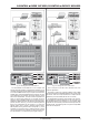
B-CONTROL FADER BCF2000/B-CONTROL ROTARY BCR2000 USB-Mode U-3: USB-Mode U-2: Fig. 4.2: Routing and use in USB mode 2 Fig. 4.3: Routing and use in USB mode 3 Your B-CONTROL sends MIDI data to the computer and receives parameter feedback, provided that the software you are controlling supports this function. MIDI IN and OUT A are available as a 16-channel MIDI interface for your computer. OUT B functions as MIDI THRU and forwards MIDI IN data unchanged.
B-CONTROL FADER BCF2000/B-CONTROL ROTARY BCR2000 USB-Mode U-4 (expanded): Fig. 4.4: Application in USB mode 4 (expanded) 4.1.2 Stand-alone modes The stand-alone modes come into play when the B-CONTROL is not used as a USB-controller for controlling PC applications but as a pure MIDI controller. With all stand-alone modes, all MIDI connectors can be used simultaneously, and these modes differ only in how the data is transmitted on the MIDI outputs.
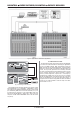
B-CONTROL FADER BCF2000/B-CONTROL ROTARY BCR2000 Stand Alone-Mode S-1: Stand Alone-Mode S-2: Fig. 4.6: Routing and use in stand-alone mode 1 Fig. 4.7: Routing and use in stand-alone mode 2 S-1 is probably the most frequently used standard operating mode among the stand-alone applications. We recommend using it when you for example want to control two sound generators from your B-CONTROL, whereby both sound generators are played simultaneously from a master keyboard.
B-CONTROL FADER BCF2000/B-CONTROL ROTARY BCR2000 Stand Alone Mode S-4: Stand Alone-Mode S-3: Fig. 4.8: Routing and use in stand-alone mode 3 In this mode, MIDI data from the BCF2000/BCR2000 is mixed with the data coming in at the MIDI input (merge function), but is exported exclusively on output A. Only control data of the B-CONTROL is available at output B.
B-CONTROL FADER BCF2000/B-CONTROL ROTARY BCR2000 Parameter feedback is enabled in all stand-alone modes. Other stand-alone modes may cause undesirable MIDI loops. In standalone mode 3, the control data of your B-CONTROL is routed to the MIDI output B without the merge function. Your B-CONTROL can also control your computer via MIDI (without a USB connection) as long as your computer features a MIDI interface. In this case, all stand-alone modes can be used.
B-CONTROL FADER BCF2000/B-CONTROL ROTARY BCR2000 + Initially, all settings made here are stored temporarily! s Release EDIT; you are now in the EDIT mode. s Using the push encoders, you can now assign MIDI commands to the selected control element. You will find all possible MIDI function in tables 4.1 and 4.2, including all accompanying explanations. s If you want to assign MIDI data to additional control elements, just press and hold the EDIT button and move one of the control elements.
B-CONTROL FADER BCF2000/B-CONTROL ROTARY BCR2000 Tab. 4.2: Assignment of the push encoders in EDIT mode (CONTINUOUS types) Table explanation: All settings in the EDIT mode are made by turning the push encoders. Pressing the push encoder displays its current value. In addition, the setting options depend on whether the selected control element is a SWITCH type or CONTINUOUS type. In the EDIT mode, Push Encoder 1 selects (by turning) the type of command assigned to a control element.
B-CONTROL FADER BCF2000/B-CONTROL ROTARY BCR2000 2d- Just like 2d, but when the value is 0, no LED lights up. Bar Bar display: when the value is changed, all LEDs light up successively (for volume etc.). Bar- Just like bar display, but when the value is 0, no LED lights up. Sprd Spread: When the value is 0, the upper middle LED lights up; when the value is increased, the LED circle gradually lights up in both directions (left and right).
B-CONTROL FADER BCF2000/B-CONTROL ROTARY BCR2000 + The settings in the global setup menu take effect can also be set (release dynamic). Therefore, you can limit the immediately and do not have to be separately stored. modulation range (FX depth) using After Touch. MMC: MIDI Machine Control data is only assignable to button elements. Operating Mode: The operating modes are described in chapter 4.1. You can select USB modes U-1 to U-4 and stand-alone modes S-1 to S-4.
B-CONTROL FADER BCF2000/B-CONTROL ROTARY BCR2000 Panic Reset: This function resets the most important MIDI data to their factory settings. s Press EDIT and keep it pressed. s Now press EXIT. The reset is performed as soon as you press EXIT. PAnC (for Panic) appears in the display. s As soon as the reset is over, your B-CONTROL goes automatically into the play mode, and the current preset is shown in the display.
B-CONTROL FADER BCF2000/B-CONTROL ROTARY BCR2000 5. APPENDIX Table 5.1: Standard MIDI Controller 5.
B-CONTROL FADER BCF2000/B-CONTROL ROTARY BCR2000 6. SPECIFICATIONS USB INTERFACE Type MIDI INTERFACE Type Full-speed 12 MBit/sec. USB MIDI class-compliant 5-pin DIN connectors IN, OUT A, OUT B/THRU CONTROL ELEMENTS BCF2000 Controls 8 motorized 100-mm faders 8 infinitely variable push encoders with LED rings Keys 20 keys 10 system keys (4x Encoder Group, 4x programming, 2x Preset) Table 5.
B-CONTROL FADER BCF2000/B-CONTROL ROTARY BCR2000 7. WARRANTY § 1 WARRANTY CARD/ONLINE REGISTRATION To be protected by the extended warranty, the buyer must complete and return the enclosed warranty card within 14 days of the date of purchase to BEHRINGER Spezielle Studiotechnik GmbH, in accordance with the conditions stipulated in § 3. Failure to return the card in due time (date as per postmark) will void any extended warranty claims.
FEDERAL COMMUNICATIONS COMMISSION COMPLIANCE INFORMATION B-CONTROL FADER BCF2000/ FADER BCF2000-WH/ROTARY BCR2000 Responsible party name: MUSIC Group Services USA, Inc. Address: 18912 North Creek Parkway, Suite 200 Bothell, WA 98011, USA Phone/Fax No.