
Tus neeg siv phau ntawv
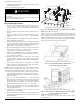


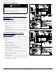
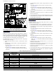


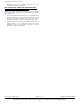
Table Of Contents
- Installation Instructions
- NOTE: Read the entire instruction manual before starting the installation.
- TABLE OF CONTENTS
- SAFETY CONSIDERATIONS
- SEQUENCE OF OPERATION
- INTRODUCTION
- DESCRIPTION AND USAGE
- a. In the Side-by-Side, upflow and downflow applications, reference the furnaces from the front, as you would see them in the upflow application. (See Fig. 2 and Fig. 3) The LH furnace is the Main furnace and the RH furnace is the Secondary furnace.
- b. In the Back-to-Back, upflow, downflow and horizontal applications, reference the furnaces from the side of the external extension harness. The LH furnace is the Main furnace and the RH furnace is the Secondary furnace, as you would see them in the...
- Fig. 1 – External Extension
- SECTION 1
- DUCT CONNECTIONS - ALL MODELS
- ELECTROSTATIC DISCHARGE (ESD) PRECAUTION
- 1. Disconnect all power to the furnace. DO NOT TOUCH THE CONTROL OR ANY WIRE CONNECTED TO THE CONTROL PRIOR TO DISCHARGING YOUR BODY’S ELECTROSTATIC CHARGE TO GROUND.
- 2. Firmly touch a clean, unpainted, metal surface of the furnace chassis which is close to the control. Tools held in a person’s hand during grounding will be satisfactorily discharged.
- 3. After touching the chassis you may proceed to service the control or connecting wires as long as you do nothing that recharges your body with static electricity (for example; DO NOT move or shuffle your feet, DO NOT touch ungrounded objects, etc).
- 4. If you touch ungrounded objects (recharge your body with static electricity), firmly touch furnace again before touching control or wires.
- 5. Use this procedure for installed and uninstalled (ungrounded) furnaces.
- 6. Before removing a new control from its container, discharge your body’s electrostatic charge to ground to protect the control from damage. If the control is to be installed in a furnace, follow items 1 through 5 before bringing the control or yo...
- 7. An ESD service kit (available from commercial sources) may also be used to prevent ESD damage.
- SECTION 2
- GENERAL - ALL ORIENTATIONS
- Install furnaces
- 1. Select two identical heating and airflow furnaces. (See Table 2 or Table 3)
- 2. Remove bottom closure panels from both furnaces. (See Fig. 5)
- a. Remove main and blower access doors.
- b. Remove screws from front filler panel.
- c. Rotate front filler panel downward to remove.
- d. Remove bottom closure panel and set aside.
- e. Reinstall front filler panel and bottom closure panel (when used)
- Install furnaces
- GENERAL - ALL ORIENTATIONS
- .
- .
- .
- Fig. 6 – Location of Foam Strips
- UPFLOW INSTALLATION
- 5. Remove the 7/8-in. (22 mm) knockout in the mating side of each furnace blower compartment. Remove one right side knockout from one furnace and the left side knockout from the other furnace. The furnace with the right side knockout removed will bec...
- 6. For side-by-side applications insert one snap bushing through each 7/8-in. (22 mm) knockout.
- 7. Position furnaces against each other on common return-air plenum (See Fig. 2). For side-by-side installations, adjust and shim each furnace to align 7/8-in. (22 mm) knockout in blower compartment, which will be used for wire routing between furnaces.
- 8. Drill two 1/8-in. (3 mm) holes, approximately 1-in. (25 mm) below discharge air flange, from inside top of discharge opening and through both furnaces.(See Fig. 7)
- 9. Drive 1 factory-supplied No. 6 x 3/4-in. (19 mm) LG screw through each hole and tighten until furnaces are secure and foam strips have sealed gap between furnaces.
- 10. Bend or remove flanges on supply air outlet of furnace as shown in furnace installation instructions.
- 11. Install indoor coil(s) and/or common supply plenum on supply air outlet of furnace. Seal all duct connections to furnace with code approved tape or sealant.
- 12. Connect common return plenum on furnace. Seal all duct connections to furnace with code approved tape or sealant.
- 13. Refer to the furnace installation instructions to complete the remaining furnace installation.
- Fig. 7 – Furnaces Together at Discharge Opening
- DOWNFLOW INSTALLATIONS
- 1. Remove the 7/8-in. (22 mm) knockout in the mating side of each furnace blower compartment. Remove one right side knockout from one furnace and the left side knockout from the other furnace. The furnace with the right side knockout removed will bec...
- 2. Insert one snap bushing through each 7/8-in. (22 mm) knockout.
- 3. Bend or remove flanges on supply air outlet of furnace as shown in furnace installation instructions
- 4. Position furnaces in the downflow position on the entering air-side of indoor coils and or common supply plenum. If no approved cased indoor coil is used, install the furnaces on accessory combustible floor bases. For side-by-side installations, a...
- 5. Drill two 1/8-in. (3 mm) holes, approximately 1-in. (25 mm) below return air flange, from inside top of return air opening and through both furnaces. (See Fig. 8)
- 6. Drive 1 factory-supplied No. 6 x 3/4-in. (19 mm) LG screw through each hole and tighten until furnaces are secure and foam strips have sealed gap between furnaces.
- 7. Connect common return plenum to furnaces. Seal all duct connections to furnace with code approved tape or sealant.
- Fig. 8 – Attaching Furnaces Together at Return Air Opening
- HORIZONTAL INSTALLATION
- General
- Attic Platform Back to Back Installations for Condensing Furnaces and Non-Condensing Furnaces
- 1. Construct a platform from 3/4-in. (19 mm) (nominal plywood), extending out 30 inches (762 mm) from the front of each furnace. (See Fig. 9 - Fig. 11)
- 2. Maintain all clearances to combustibles per the furnace Installation, Start-up and Operating Instructions.
- 3. Follow all additional building codes.
- 4. Long truss spans may require additional support along the bottom chord of the truss. Consult the truss manufacturer’s guidelines for engineering assistance.
- 5. Long rafter or attic joist spans may require additional support along the bottom of the rafter or joist. Consult local or regional building codes for design and loading requirements.
- 6. Lay both furnaces in the required orientation with the knockouts in the blower compartment facing upward.
- 7. Drill two 1/8-in. (3 mm) holes, approximately 1-in. (25 mm) below return air flange, from inside top of return air opening and through both furnaces. (See Fig. 8)
- 8. Drive 1 factory-supplied No. 6 x 3/4-in. (19 mm) LG screw through each hole and tighten until furnaces are secure and foam strips have sealed gap between furnaces.
- 9. Drill two 1/8-in. (3 mm) holes, approximately 1-in. (25 mm) below discharge air flange, from inside top of discharge opening and through both furnaces. (See Fig. 7)
- 10. Drive 1 factory-supplied No. 6 x 3/4-in. (19 mm) LG screw through each hole and tighten until furnaces are secure and foam strips have sealed gap between furnaces.
- 11. Install indoor coil(s) and/or common supply plenum on supply air outlet of furnace. Seal all duct connections to furnace with code approved tape or sealant.
- 12. Connect common return plenum to furnaces. Seal all duct connections to furnace with code approved tape or sealant.
- 13. Follow individual furnace installation instructions for horizontal applications. This includes, but not limited to: condensate trap, condensate/inducer housing tubing, pressure switch tubing venting and electrical connections.
- 14. Go to Connect Electrical Components.
- Horizontal Suspended Installation for Condensing Furnaces
- 1. Furnaces may be suspended using two (2) pieces of 1-1/2-in. x 1-1/2-in. x 1/4-in. (38 mm x 38 mm x 6 mm) thick cold rolled angle iron underneath each furnace and four (4) 3/8-in. (10 mm) diameter threaded rods. Angle iron must be positioned as sho...
- 2. Unistrut or similar material may be used, provided that the furnaces do not sag in the middle or bend or twist at the support ends. The support material must be secured to the bottom of each furnace in a manner similar to securing angle iron to th...
- 3. Each piece of angle iron must be secured to the bottom of each furnace with at least two (2) No..8 x 3/4-in. (19 mm) sheet metal screws.
- 4. Drill four 5/16-in. (8 mm) holes through the angle iron and through each side of the casing for the suspension rods as shown in Fig. 12.
- 5. Lay furnaces back-to-back on a flat surface with 7/8 knock-outs facing upward.
- 6. Drill two 1/8-in. (3 mm) holes, approximately 1-in. (25 mm) below return air flange, from inside top of return air opening and through both furnaces. (See Fig. 8)
- 7. Drive one factory-supplied No. 6 x 3/4-in. (19 mm) LG screw through each hole and tighten until furnaces are secure and foam strips have sealed gap between furnaces.
- 8. Drill two 1/8-in. (3 mm) holes, approximately 1-in. (25 mm) below discharge air flange, from inside top of discharge opening and through both furnaces. (See Fig. 7)
- 9. Drive one factory-supplied No. 6 x 3/4-in. (19 mm) LG screw through each hole and tighten until furnaces are secure and foam strips have sealed gap between furnaces.
- 10. Insert the 1/4-in. (6 mm) threaded rod through each hole in the furnace and through the angle iron. Secure the threaded rod to the angle iron with a washer, lock washer and nut.
- 11. To prevent the rod from falling out of the furnace, install a washer, lock washer and nut on portion of the threaded rod above the furnace.
- 12. Raise and suspend the furnaces using the appropriate lift and secure the threaded rod with the appropriate field-supplied hardware. Use locking hardware such as lock washers and jamb nuts to prevent nuts or bolts from loosening.
- 13. Install indoor coil(s) and/or common supply plenum on supply air outlet of furnace. Seal all duct connections to furnace with code approved tape or sealant.
- 14. Connect common return plenum to furnaces. Seal all duct connections to furnace with code approved tape or sealant.
- 15. Follow individual furnace installation instructions for horizontal applications. This includes, but not limited to: condensate trap, condensate/inducer housing tubing pressure switch tubing venting and electrical connections.
- 16. Go to Connect Electrical Components.
- Horizontal, Suspended Installation for Non-Condensing Furnaces
- 1. Furnaces may be suspended using two (2) pieces of 1-1/2-in. x 1-1/2-in. x 1/4-in. thick cold rolled angle iron underneath each furnace and four (4) 3/8-in. (10 mm) diameter threaded rods. (See Fig. 13)
- 2. Allow for at least 9 inches (228 mm) in front of each door for door removal.
- 3. Each piece of angle iron must be secured to the bottom of each furnace with at least two (2) No. 8 x 3/4-in. (19 mm) sheet metal screws.
- 4. Maintain all clearances to combustibles per the furnace Installation, Start-up and Operating Instructions.
- 5. Unistrut or similar material may be used, provided that the furnaces do not sag in the middle or bend or twist at the support ends. The support material must be secured to the bottom of each furnace in a manner similar to securing angle iron to th...
- 6. For all horizontal applications: Return air can only be connected to bottom opening of furnace. A common return air plenum is required for proper auxiliary limit switch operation.
- 7. Apply two factory-supplied foam strips to the back of each furnace. Locate strips equal distance from top and bottom as shown in Fig. 6. Trim off excess material.
- 8. Determine which side of furnace will be used to route external extension harness. Remove 7/8-in. diameter accessory hole knockouts in blower compartment side selected to attach harness to. (See Fig. 1)
- 9. Position furnaces back-to-back on attic platform or suspended supports. Adjust and shim each furnace to align both furnaces. Follow all clearance to combustible material.
- 10. If furnaces are installed closer than 12 inches above a deck made from combustible material, provide rollout protection as shown in the furnace installation instructions. The bottom closure pan may be used for this purpose.
- 11. Drill two 1/8-in. holes, approximately 1 in. (25 mm) below discharge flange, from inside top of discharge opening and through both furnaces. (See Fig. 7) Drill two 1/8-in. holes, approximately 1 in. (25 mm) below return air flange, from inside to...
- 12. Drive one factory-supplied No. 6 x 3/4-in. LG screw through each hole and tighten until furnaces are secure and foam strips have sealed gap between furnaces.
- 13. Connect return- and supply-air ducts to furnaces. Seal duct connections to prevent air leakage.
- 14. Move 115V junction box JB in either furnace from left-hand side to right-hand side if required. Refer to furnace installation instructions for complete details.
- 15. Go to Connect Electrical Components.
- Fig. 9 – Attic Installation of Furnace for Condensing Furnace ONLY
- Fig. 10 – Attic Installation of Back-to-Back Furnace for Non-Condensing Furnace ONLY
- Fig. 11 – Attic Installation of Horizontal Furnace Stacked Together for Non-Condensing Furnaces ONLY.
- Fig. 12 – Suspended Installation for Condensing Furnace ONLY
- Fig. 13 – Suspended Back-to-Back for Non-Condensing Furnaces ONLY.
- Fig. 14 – Suspended Installation for Horizontal Furnaces Stacked Together for Non-Condensing Furnaces ONLY.
- Horizontal, Stacked Together for Non-Condensing ONLY
- 1. Construct a platform from 3/4-in. (nominal plywood), extending out 30 inches (762 mm) from the front of each furnace.
- 2. Maintain all clearances to combustibles per the furnace Installation, Start-up and Operating Instructions.
- 3. Follow all additional building codes.
- 4. Long truss spans may require additional support along the bottom chord of the truss. Consult the truss manufacturer’s guidelines for engineering assistance.
- 5. Long rafter or attic joist spans may require additional support along the bottom of the rafter or joist. Consult local or regional building codes for design and loading requirements.
- 1. Furnaces may be suspended using two (2) pieces of 1-1/2-in. x 1-1/2-in. x 1/4-in. thick cold rolled angle iron underneath the furnaces and four (4) 3/8-in. diameter threaded rods.
- 2. Allow for at least 9 inches (229 mm) in front of each door for door removal.
- 3. Each piece of angle iron must be secured to the bottom of each furnace with at least two (2) #8 x 3/4-in. sheet metal screws.
- 4. Maintain all clearances to combustibles per the furnace Installation, Start-up and Operating Instructions.
- 5. Unistrut or similar material may be used, provided that the furnaces do not sag in the middle or bend or twist at the support ends. The support material must be secured to the bottom of each furnace in a manner similar to securing angle iron to th...
- 6. For all horizontal applications: Return air can only be connected to bottom opening of furnace.
- 7. Apply 2 factory-supplied foam strips to mating side of each furnace. Locate strips equal distance from top and bottom as shown in Fig. 6.
- 8. Remove 7/8-in. diameter accessory hole knockouts in blower compartment from mating sides of furnaces.
- 9. Insert a plastic snap bushing through the 7/8-in. K.O. from the outside of the casing.
- 10. Position furnaces on top of each other on platform or suspended supports. Adjust and shim each furnace to align 7/8-in. diameter holes in both furnaces.
- 11. Drill two 1/8-in. holes, approximately 1 in. (25 mm) below discharge flange, from inside top of discharge opening and through both furnaces. (See Fig. 7) Drill two 1/8-in. holes, approximately 1 in. (25 mm) above return air opening flange, from i...
- 12. Drive 1 factory-supplied screw through each hole and tighten until furnaces are secure and foam strips have sealed gap between furnaces.
- 13. Connect return- and supply-air ducts to furnaces. Seal duct connections to prevent air leakage.
- 14. Move 115-v junction box JB in RH furnace (as viewed from the upflow position) from left-hand side to right-hand side. Refer to furnace installation instructions for complete details.
- 15. Go to Connect Electrical Components.
- SECTION 3
- CONNECT ELECTRICAL COMPONENTS
- 115-VAC Connections to Furnace
- a. Both LEDs are on continuously: System phasing is okay.
- b. One or both LEDs are rapidly flashing:
- (1.) Line voltage polarity is reversed.
- (2.) Furnace(s) are not grounded
- (3.) Transformer polarity is reversed.
- c. One LED is off, one LED is on continuously:
- (1.) The 24-VAC circuit is inoperative on furnace with LED light off.
- (2.) Check transformers, auxiliary limits, and door switches in both furnaces and correct problem.
- (3.) Reconnect lead at TWIN/TEST terminal of LH furnace and observe LED at each furnace. The LEDs will glow steady for proper phasing.
- 115-VAC Connections to Furnace
- TWINNING KIT HARNESS CONNECTIONS
- 1. Verify the knockouts are removed from the same side of each furnace blower compartment.
- 2. Remove the locknut from each end of the 1/2-in. BX connector
- 3. Route the 4-pin plug and the 2-pin plug of the Main furnace end of the Extension harness one at a time through the knockout into the Main furnace blower compartment.
- 4. Insert the plugs through the locknut of the 1/2-in. BX connector and tighten the locknut on the BX connector.
- 5. Route the 4-pin plug and the 2-pin plug of the Secondary furnace end of the Extension harness one at a time through the knockout into the Secondary furnace blower compartment.
- 6. Insert the plugs through the locknut of the 1/2-in. BX connector and tighten the locknut on the BX connector.
- Install Main Twinning Kit Harness
- 7. Connect the Yellow wire labeled “TEST” to the “TEST/TWIN” terminal on the Main furnace control board.
- 8. Remove the Red transformer lead from the “SEC-1/24 VAC” terminal on the Main furnace control board.
- 9. Connect the Red transformer lead removed from the Main furnace control board to the Red wire labeled “TRANS” on the Main Twinning Kit harness.
- 10. Connect the Orange wire labeled “SEC-1/24 VAC” to the “SEC-1/24 VAC” terminal on the Main furnace control board.
- 11. Connect the Black wire with the fork terminal labeled “C” on the TKR to the “COM/24V” terminal on the thermostat strip of the Main furnace control board.
- 12. Install the Twinning Kit Relay, (TKR)
- a. For single-stage operation of single-stage furnaces connect the White wire with the fork terminal labeled “W” on the TKR to the “W” terminal on the thermostat strip of the Main furnace control board. See Fig. 20.
- b. For staged operation of single-stage furnaces with a two-stage thermostat, remove the fork terminal from the terminal on the TKR and discard. The thermostat W2 lead is spliced into this wire. Refer to Fig. 21 and Thermostat Connections section for...
- c. For operation of two-stage furnaces with a single-stage or two-stage thermostat, connect the White wire with the fork terminal on the TKR to the “W/W1” terminal on the thermostat strip of the Main furnace control board. Refer to Fig. 19 and Th...
- Install Secondary Twinning Kit Harness
- 1. Connect the Yellow wire labeled “TEST SECONDARY” to the “TEST/TWIN” terminal on the Secondary furnace control board.
- 2. Connect the Black wire with the fork terminal labeled “C SECONDARY” to the “COM/24V” terminal on the thermostat strip of the Secondary furnace control board.
- 3. Connect the White wire with the fork terminal labeled “W SECONDARY” to the “W” or “W/W1” terminal on the thermostat strip of the Secondary furnace control board.
- 4. Connect the Red wire with the fork terminal labeled “R SECONDARY” to the “R” terminal on the thermostat strip of the Secondary furnace control board.
- 5. Remove the Red transformer lead from the “SEC-1/24 VAC” terminal on the Secondary furnace control board.
- 6. Connect the Red wire with the piggy-back terminal labeled “SEC-1/24 VAC” on the ILR to the “SEC-1/24 VAC” terminal on the Secondary furnace control board.
- 7. Connect the Red transformer lead to the piggy back terminal of the Red wire connected to the “SEC-1/24 VAC” terminal on the Secondary furnace control board.
- 8. Remove the Blue transformer lead from the “SEC-2/COM” terminal on the Secondary furnace control board.
- 9. Connect the Black wire with the piggy-back terminal labeled “C” on the ILR to the “SEC-1/24 VAC” terminal on the Secondary furnace control board.
- 10. Connect the Blue transformer lead to the piggy back terminal of the Black wire connected to the “SEC-1/24 VAC” terminal on the Secondary furnace control board.
- a. Mount Twinning Kit Relay and Interlock Relay on furnace blower housing as shown.
- b. Twining Kit Relay (TKR) mounts on LH Furnace blower housing
- c. Interlock Relay (ILR) mounts on RH furnace blower housing.
- Fig. 15 – Mounting Twinning Kit Relay
- Fig. 16 – Extension Harness
- Fig. 17 – Main Harness
- Fig. 18 – Secondary Harness
- Fig. 19 – Example of Furnace Control
- CONNECT ELECTRICAL COMPONENTS
- CONNECT ELECTRICAL COMPONENTS - COOLING
- 1. Connect the L1 lead of the field-supplied transformer line voltage lead to L1 on Main furnace control board.
- 2. Connect the Neutral lead of the field-supplied transformer to an open Neutral terminal on the Main furnace control board.
- For Single-Stage A/C Operation with Single-Stage Thermostat See Fig. 20.
- 1. Connect one coil terminal of the field-supplied pilot duty relay to the “COM/24V” terminal of the furnace control board.
- 2. Connect the other coil terminal of the field-supplied pilot duty relay to the “Y or Y/Y2” terminal of the furnace control board.
- 3. Connect the R terminal of the field-supplied transformer to the open contract of the pilot duty relay.
- 4. Connect the other open contact to the wire for Y terminal of the contactor(s).
- 5. Connect the Common terminal of the contactor(s) to the C terminal of the field supplied transformer.
- For Two-Stage A/C Operation with a Two-Stage thermostat. See Fig. 21.
- 1. Connect one coil terminal of each of the pilot duty relay together.
- 2. Connect these two terminals to the “COM/24V” terminal of the furnace control board.
- 3. Select one of the relays to be the relay for first stage cooling. Connect the coil terminal of this relay to the “Y or Y/Y2” terminal of the furnace control board.
- 4. The other relay is the second stage cooling relay. The coil terminal of this relay will connect to the “Y/Y2” terminal of the thermostat. Do not connect the terminal to the Y1 terminal on the furnace control board.
- 5. Connect the R terminal of the field-supplied transformer to the open contract of each pilot duty relay.
- 6. Connect the other open contact of the first stage cooling relay to the wire for Y terminal of the first stage contactor.
- 7. Connect the other open contact of the first stage cooling relay to the wire for Y terminal of the second stage contactor.
- 8. Connect the Common terminal of the contactor(s) to the C terminal of the field supplied transformer.
- THERMOSTAT CONNECTIONS
- Single-Stage Furnaces with Single-Stage Thermostat (Field Supplied) See Fig. 20 and Table 4
- 1. Connect thermostat W lead to “W” on the Main furnace control board.
- 2. Connect thermostat Y lead to “Y or Y/Y2” on the Main furnace control board.
- 3. Connect the G thermostat lead to the “G” terminal on the Main furnace control board.
- 4. Connect thermostat R lead to “R” terminal on Main furnace control.
- 5. Connect thermostat C or COM lead to the “COM/24V” terminal on the Main furnace control board.
- Single-Stage Furnaces and A/C with Two-Stage thermostat (Field Supplied) See Fig. 21 and Table 4
- 1. Connect thermostat W1 lead to “W” on the Main furnace control board.
- 2. Connect thermostat W2 lead to White wire labeled “W” on the twinning kit relay (TKR).
- 3. Connect first stage cooling thermostat lead Y1 to “Y or Y/Y2” on the Main furnace control board.
- 4. Connect the second stage cooling thermostat lead Y/Y2 to the pilot duty relay coil for the second stage contactor.
- 5. Connect the G thermostat lead to the “G” terminal on the Main furnace control board.
- 6. Connect thermostat R lead to “R” terminal on Main furnace control.
- 7. Connect thermostat C or COM lead to the “COM/24V” terminal on the Main furnace control board.
- 8. Connect the G thermostat lead to the “G” terminal on the Main furnace control board.
- 9. Connect thermostat R lead to “R” terminal on Main furnace control.
- 10. Connect thermostat C or COM lead to the “COM/24V” terminal on the Main furnace control board.
- Fig. 20 – Single-Stage Furnace with Single-Stage Thermostat
- Fig. 21 – Single-Stage Furnaces with Two-Stage Thermostat
- Fig. 22 – Two-Stage Furnace
- Two−Stage Furnaces with Single-Stage Thermostat (Field Supplied)
- 1. Connect thermostat W lead to “W/W1” on Main furnace control board.
- 2. On Main/Primary Furnace Enable 1-stage heating thermostat on control board by:
- a. For boards with DIP switches, turn SW1-2 on furnace control OFF, see Fig. 22.
- b. For boards with 3 digit display, navigate to (Htt) and select (1St), see Fig. 22. See furnace installation manual for additional instructions.
- 3. On RH/Secondary furnace, enable 2-stage thermostat on control board by:
- a. For boards with DIP switches, turn SW1-2 on furnace control ON, see Fig. 22.
- b. For boards with 3 digit display, navigate to (Htt) and select (2St), see Fig. 22. See furnace installation manual for additional instructions.
- 4. Connect cooling thermostat lead Y to “Y/Y2” on the Main furnace control board.
- 5. Connect the G thermostat lead to the “G” terminal on the Main furnace control board.
- 6. Connect thermostat R lead to “R” terminal on Main furnace control.
- 7. Connect thermostat C or COM lead to the “COM/24V”terminal on the Main furnace control board.
- Two−Stage Furnaces with Two−Stage Thermostat (Field Supplied)
- 1. Connect thermostat W to “W/W1” on Main furnace control board.
- 2. Connect thermostat W2 to “W2” on Main furnace control board.
- 3. On Main/Primary Furnace Enable 2-stage heating thermostat on control board by:
- a. For boards with DIP switches, turn SW1-2 on furnace control ON, see Fig. 22.
- b. For boards with 3 digit display, navigate to (Htt) and select (2St), see Fig. 22. See furnace installation manual for additional instructions.
- 4. On RH/Secondary furnace, enable 2-stage thermostat on control board by:
- a. For boards with DIP switches, turn SW1-2 on furnace control ON, see Fig. 22.
- b. For boards with 3 digit display, navigate to (Htt) and select (2St), see Fig. 22. See furnace installation manual for additional instructions.
- 5. Connect first stage cooling thermostat lead Y1 to “Y/Y2”on the Main furnace control board.
- 6. Connect the second stage cooling thermostat lead Y/Y2 to the pilot duty relay coil for the second stage contactor.
- 7. Connect the G thermostat lead to the “G” terminal on the Main furnace control board.
- 8. Connect thermostat R lead to “R” terminal on Main furnace control.
- 9. Connect thermostat C or COM lead to the “COM/24V” terminal on the Main furnace control board.
- Table 4 – Single-Stage Thermostat Connections
- Table 5 – Two-Stage Furnace Thermostat Connections
- Single-Stage Furnaces with Single-Stage Thermostat (Field Supplied) See Fig. 20 and Table 4
- VENTING
- GAS SUPPLY PIPING
- CONDENSATE DRAIN CONNECTIONS
- START-UP AND ADJUSTMENT
- 1. Shut off all power and gas to both furnaces.
- 2. For control boards with display and push-buttons, set the twinning menu item on the Secondary Furnace to SEC as shown on wiring label. For two-stage furnaces, also set the heating thermostat type (HTT) as shown on wiring label.
- 3. Set the heating blower speed to the same setting or tap on both furnaces. Repeat for cooling and continuous fan speed settings.
- 4. Attach twinning connection wiring label above the existing furnace wiring label on the inside of the LH furnace blower door. Use the following labels for the following applications:
- 5. Attach twinning reference label 348926-101 on the outside of blower access door of RH furnace.
- Fig. 23 – Example of Twinning Reference Label
- 6. Manually close the door switch on both furnaces.
- 7. Turn on power and gas to furnaces.
- 8. For control boards with display and pushbuttons, observe the 3 digit display on both furnaces. When the display is showing system status, the dots at the bottom of the display indicate the communication status of the primary and secondary furnaces...
- Fig. 24 – Twinning Communication Indicator
- 9. Using the appropriate section below, operate furnaces through two cycles in each mode to confirm correct operation by operating only the thermostat.
- a. Single- or two-stage gas heating thermostat R to W/W1 for low-heat. Single-stage thermostat with adaptive heating mode causes furnace to operate in low-heat mode for up to 16 minutes, and then furnace automatically switches to high-heat. First sta...
- b. First and second-stage of two-stage heating thermostat R to W/W1 and W2 for high-heat.
- c. Thermostat R to G for continuous fan. (SeeTable 4 or Table 5)
- d. Cooling thermostat R to G and Y or Y/Y2 for single stage cooling blower or for two-stage cooling high-cool blower.
- 10. Reinstall doors on both furnaces.
- 11. Instruct user in operation of furnaces and thermostat.
- SEQUENCE OF OPERATION
- SINGLE-STAGE HEAT, SINGLE-STAGE FURNACES WITH SINGLE-STAGE THERMOSTAT
- TWO-STAGE HEAT, SINGLE-STAGE FURNACES WITH TWO-STAGE THERMOSTAT
- 1. The two-stage thermostat determines if furnaces are operating in first-stage heat (LH furnace operates in heat while RH furnace blower operates but RH furnace is not heating) or if furnaces are operating in second-stage heat (both furnaces operate...
- 2. Operation in all modes (sequence of operation) is the same for twinned furnaces as for an individual furnace. See furnace Installation, Start-Up, and Operating Instructions for more information on sequence of operation.
- TWO-STAGE HEAT, TWO-STAGE FURNACES WITH SINGLE-STAGE THERMOSTAT
- Fig. 25 – Furnace Thermostat Switch
- Table 6 – Setup Selection
- 1. LH furnace control determines whether furnaces are both operating in low-heat or high-heat, depending on the control’s adaptive gas heating mode when the R-to-W/W1 circuit is closed in LH furnace.
- 2. Operation in all modes (sequence of operation) is the same for twinned furnaces as for an individual furnace. See furnace Installation, Start-Up, and Operating Instructions for more information on sequence of operation.
- TWO-STAGE HEAT, TWO-STAGE FURNACES WITH TWO-STAGE GAS-HEAT THERMOSTAT
- 1. The two-stage thermostat (NOT the furnace control’s adaptive gas heating mode) determines whether furnaces are both operating in low-heat or high-heat, depending on whether one or both thermostat stages (W/W1 or W/W1 and W2) are calling for heat.
- 2. Operation in all modes (sequence of operation) is the same for twinned furnaces as for an individual furnace. See furnace Installation, Start-Up, and Operating Instructions for more information on sequence of operation.
- NOTE: Read the entire instruction manual before starting the installation.

AGATWNDTE01C: Installation Instructions
Manufacturer reserves the right to change, at any time, specifications and designs without notice and without obligations.
17
5. Attach twinning reference label 348926-101 on the outside of
blower access door of RH furnace.
A221467
Fig. 23 – Example of Twinning Reference Label
6. Manually close the door switch on both furnaces.
7. Turn on power and gas to furnaces.
8. For control boards with display and pushbuttons, observe the 3 digit
display on both furnaces. When the display is showing system
status, the dots at the bottom of the display indicate the
communication status of the primary and secondary furnaces as
shown in
Fig. 24.
• Solid light = unit is communicating
• Flashing light = unit has lost communication
• No light = unit is not communicating
If the lights do not activate, check TWIN wire connection and confirm
that the twinning (tnn) selection is set correctly on each furnace. See
wiring label for correct settings. Next, cycle power.
NOTE: The indicators are not valid while the display is showing a fault
code.
A221466
Fig. 24 – Twinning Communication Indicator
9. Using the appropriate section below, operate furnaces through two
cycles in each mode to confirm correct operation by operating only
the thermostat.
a. Single- or two-stage gas heating thermostat R to W/W1 for
low-heat. Single-stage thermostat with adaptive heating mode
causes furnace to operate in low-heat mode for up to 16 minutes,
and then furnace automatically switches to high-heat. First stage
of a two-stage thermostat without adaptive heating mode causes
furnace to operate in low-heat mode indefinitely.
b. First and second-stage of two-stage heating thermostat R to
W/W1 and W2 for high-heat.
c. Thermostat R to G for continuous fan. (See
Table 4 or Table 5)
d. Cooling thermostat R to G and Y or Y/Y2 for single stage
cooling blower or for two-stage cooling high-cool blower.
10. Reinstall doors on both furnaces.
11. Instruct user in operation of furnaces and thermostat.
SEQUENCE OF OPERATION
See furnace twinning connection and schematic wiring diagrams while
reviewing sequence of operation.
Twinning operation is controlled by LH or MAIN furnace. The
TWIN/TEST connection wire ensures the two furnaces coordinate their
blower and heating stage operation. When either furnace requires blower
operation, both furnace blowers operate at same speed. Both furnaces
operate simultaneously in the same mode: heat, cool, or continuous fan.
Exceptions can occur if a safety switch on either furnace is opened by a
problem (such as pressure switch, flame roll-out switch, main limit
switch, twinning kit auxiliary limit switch, or flame-proving sensor). In
such a case, the other furnace continues to operate unless open switch is
the flame roll-out, main limit, or twinning kit auxiliary limit switch, in
which case both furnaces respond.
Before performing component test, disconnect TKR yellow wire labeled
TEST from LH furnace control center TWIN/TEST terminal. After
removing yellow wire, component test can be initiated on each furnace
individually as stated in Installation, Start-Up, and Operating
Instructions.
SINGLE-STAGE HEAT, SINGLE-STAGE FURNACES
WITH SINGLE-STAGE THERMOSTAT
1. Operation in all modes (sequence of operation) is the same for
twinned furnaces as for an individual furnace. See furnace
Installation, Start-Up, and Operating Instructions for more
information on the sequence of operation.
TWO-STAGE HEAT, SINGLE-STAGE FURNACES WITH
TWO-STAGE THERMOSTAT
1. The two-stage thermostat determines if furnaces are operating in
first-stage heat (LH furnace operates in heat while RH furnace
blower operates but RH furnace is not heating) or if furnaces are
operating in second-stage heat (both furnaces operate in heat),
depending on how many thermostat stages are calling for heat. If
two-stage cooling is used, Y1 from the thermostat will initiate both
furnace blowers to the cooling speed and the first A/C unit. Y2
from the thermostat will go directly to the outdoor unit and initiate
the second A/C unit.
2. Operation in all modes (sequence of operation) is the same for
twinned furnaces as for an individual furnace. See furnace
Installation, Start-Up, and Operating Instructions for more
information on sequence of operation.
TWO-STAGE HEAT, TWO-STAGE FURNACES WITH
SINGLE-STAGE THERMOSTAT
NOTE: See Electrical Connections for control board wiring and HTT
menu setting or LHT switch setup switch depending on model. (See
Fig. 25 and Table 6)
A221465
Fig. 25 – Furnace Thermostat Switch
1. LH furnace control determines whether furnaces are both operating
in low-heat or high-heat, depending on the control’s adaptive gas
heating mode when the R-to-W/W1 circuit is closed in LH furnace.
2. Operation in all modes (sequence of operation) is the same for
twinned furnaces as for an individual furnace. See furnace
Table 6 – Setup Selection
For Controls with Display and Pushbuttons
Thermostat
Type
Menu
Selection
Main (LH)
Selection
Secondary (RH)
Both
tnn Pri SEC
One Stage
Htt 1st 2st
Two Stage
Htt 2st 2st