LCR55A Inductance, Capacitance, Resistance Meter User Manual UÊ i`iÕ}Ã >`LÕV UÊ >Õ>Ê`iÊÕÃ UÊ `iÊ`½i«
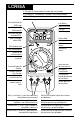
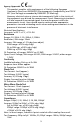
LCR55A 3-1/2 digit LCD; decimal point, function and unit indicators 3-1/2 Digit LCD ; Dezimalpunkt, Funktions- und Einheitsanzeigen LCD de 3-1/2 dígitos, punto decimal, indicadores de función y unidades LCD 3-1/2 digits ; point décimal, indicateurs de fonctions et d'unités Zero adjustment for 20 range Nullabgleich für 20 Bereich Ajuste de cero para escala de 20 Low Battery Batterie entladen Pila baja Pile déchargée hFE HmHH Mise-à-zéro pour calibre 20 Max Reading Hold k M nF FmF MAX Max Anzeig
LCR55A Operators Manual • Bedienungsanleitung • Manual de Instrucciones • Manuel d’Utilisation PN 1566247 ©2007 Amprobe. All rights reserved.
Limited Warranty and Limitation of Liability Your Amprobe product will be free from defects in material and workmanship for 1 year from the date of purchase. This warranty does not cover fuses, disposable batteries or damage from accident, neglect, misuse, alteration, contamination, or abnormal conditions of operation or handling. Resellers are not authorized to extend any other warranty on Amprobe’s behalf.
Inductance, Capacitance, Resistance Meter Contents Symbols .............................................................................................................. 1 Warnings and Precautions ................................................................................ 1 Overload Indication .......................................................................................... 2 Preparation for Use – Unpacking .....................................................................
"ÛiÀ>`Ê `V>Ì Range overload is indicated by a “OL” in the display with all other digits blanked. Overload indication is normal in the OHMS range with open circuit or too high a resistance. *Ài«>À>ÌÊvÀÊ1ÃiÊqÊ1«>V} Your shipping carton should include the LCR55A, one test lead set (one black, one red), one pair of alligator clips, one 9V battery (installed), one spare 0.1A/250V fuse (inside the case), one holster, a warranty card and this manual.
be tested in the same manner described above. Note: The test procedure of microwave oven diodes is identical to regular diodes except forward voltage drop will be higher (3 or more volts) than standard silicon diodes. LEDs may also be tested with the LCR55A in the M.W. position. Continuity Test The Continuity test checks electrical continuity between two contact points. 1. Set the Function/Range switch to R. 2.
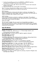
1. Set the Function/Range switch to the PNP(hFE) or NPN(hFE) position, according to the type of transistor to be measured. 2. Plug the emitter, base and collector leads of the transistor into the correct holes of test socket. 3. Read the hFE beta, (DC current gain) in the display. Note: To measure the collector-emitter current, set the function/range switch to the corresponding PNP(Icec µA) or NPN(Icec µA) position. MAX Function Push the MAX button to keep only the highest reading on the display.
P Agency Approvals: EMC This product complies with requirements of the following European Community Directives: 89/336/EEC (Electromagnetic Compatibility) and 73/23/ EEC (Low Voltage) as amended by 93/68/EEC (CE Marking). However, electrical noise or intense electromagnetic fields in the vicinity of the equipment may disturb the measurement circuit. Measuring instruments will also respond to unwanted signals that may be present within the measurement circuit.
Temperature Coefficient: ≤0.5µF: 0.1%/°C; >0.5µF: 0.2%/°C OL Protection: 0.1A/250V fast blow fuse. Inductance Ranges: 200µH, 2, 20, 200mH, 2, 20, 200H Accuracy: 200µH rg: ±(5.0%rdg +30dgt)* 2 to 200mH: ±(3.0% +20dgt)* 2 to 200H: ±(5.0% +20dgt)* *For values of Q ≤7 Test Frequency: 200µH to 2H rgs: 1000Hz; 20 and 200H ranges: 100Hz Temperature Coefficient, ≤0.5H: 0.2%/°C; >0.5H: 0.5%/°C OL Protection: 0.1A/250V fast blow fuse Transistor Test hFE Range: 0-1000 hFE Base Current: 5µA approx.
W Warning Use of an incorrect fuse could result in serious injury or even death. Failure to turn off the multimeter before installing the battery could result in damage to instrument and battery. ,i«>À All test tools returned for warranty or non-warranty repair or for calibration should be accompanied by the following: your name, company’s name, address, telephone number, and proof of purchase.
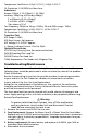
1 5 k MAX 20k 200k 20 ADJ. 2k 200 20 OFF 4 3 HOLD 200 2m H 20m 200m 2M 2 20 20M 200 NPN hFE NPN 2m M.W. (Icec A) 2000 200 F 20 2 200n 20n 2n 200p PNP hFE PNP (Icec A) EBCE LCR55A Cx Lx Hi(+) Lo(-) 2 200mA MAX FUSED Lx Cx FUSED DISCHARGE CAPACITOR BEFORE CONNECTING Rx MAX 350V 2 <1 V 4 OK OK Anode MAX 20k 200k 20 ADJ. 2k 200 20 OFF Cathode HOLD 200 2m 2 H 20m 200m 2M 3 2 Cathode 20 20M 200 Anode NPN hFE NPN 2m M.W.
3 4 3B F MAX 20k 200k 20 ADJ. 2k 200 20 OFF 2 HOLD 200 2m H 20m 200m 2M 2 20 20M 200 NPN hFE NPN 2m M.W.
LCR55A Operators Manual • Bedienungsanleitung • Manual de Instrucciones • Manuel d’Utilisation Deutsch Inductance, Capacitance, Resistance Meter German 1 Deut
Beschränkte Gewährleistung und Haftungsbeschränkung Es wird gewährleistet, dass dieses Amprobe-Produkt für die Dauer von einem Jahr ab dem Kaufdatum frei von Material- und Fertigungsdefekten ist. Diese Gewährleistung erstreckt sich nicht auf Sicherungen, Einwegbatterien oder Schäden durch Unfälle, Nachlässigkeit, Missbrauch, Änderungen oder abnormale Betriebsbedingungen bzw. unsachgemäße Handhabung. Die Verkaufsstellen sind nicht dazu berechtigt, diese Gewährleistung im Namen von Amprobe zu erweitern.
Inductance, Capacitance, Resistance Meter Inhalt Symbole ............................................................................................................. 1 Warnungen und Vorsichtsmaßnahmen ........................................................... 1 Überlastanzeige ................................................................................................ 2 Gebrauchsvorbereitung - Auspacken............................................................... 2 Meßprozeduren ....................
4LiÀ>ÃÌ>âi}i Wenn ein Signal die Bereichsgrenze überschreitet erscheint das Symbol “OL” in der Anzeige. Diese Anzeige ist normal bei Widerstandsmessung wenn Mekabel/spitzen frei stehen oder wenn der Meßwert den Bereich überschreitet. iLÀ>ÕV ÃÛÀLiÀiÌÕ}ÊÊ Õë>ViÊ Die Verpackung sollte enthalten: das LCR55A, ein Meßkabelsatz (ein schwarz, ein rot), ein Paar Krokodilklemmen, eine 9V Batterie (im Gerät), eine 0.1A/250V Ersatzsicherung (im Gerät), eine Garantiekarte und diese Anleitung.
Durchgangstest 1. Funktionsschalter auf R stellen. 2. Rotes Meßkabel mit +Rx Eingang und schwarzes mit -Rx Eingang verbinden. 3. Meßspizen mit Schaltkreis verbinden. 4. Bei R ≤100Ω wird ein akustische Signal abgegeben. Kapazitätsmessung (Fig. -3-) 1. Kondensator entladen (über 20kΩ Widerstand). 2. Rotes Meßkabel mit HI(+) Eingang und schwarzes mit LO(-) Eingang verbinden. 3. Wahlschalter auf den Kapazitätsbereich stellen der die beste Auflösung gibt. 4. Meßspitzen mit Kondensatorleitern verbinden. 5.
Anzeigesperre HOLD Taste drücken um den Meßwert auf der Anzeige festzuhalten. Der Meßwert bleibt erhalten, auch wenn die Meßspitzen vom Schaltkreis entfernt sind. HOLD Taste erneut drücken um die Anzeige freizugeben. Sicherheitsmeßkabel Die Meßkabel haben versenkte Bananenstecker um elektrischen Schock zu vermeiden. Die Meßspitzen sind zum Teil isoliert, um Kurzschlüsse in dichten Schaltungen zu vermeiden. Diese Isolation kann entfernt werden.
200Ω Bereich: ±0.5% vMW +3Dgt 2k to 2MΩ Ber.: ±(0.5% vMW +1Dgt) 20MΩ Ber.: ±(2.0% vMW +2Dgt) Überlastschutz, alle Bereiche: 350VDC oder AC eff. Leerlaufspannung, 20Ω Bereich: 6.5VDC, 200Ω Bereich: 3.0VDC, andere Bereiche: 1.2VDC Durchgangstest Akustisches Signal im 2kΩ Bereich bei R ≤30Ω Ansprechzeit: ung. 800ms Überlastschutz: 350VDC oder AC eff. Diodentest Teststrom: 1mA (approx.) Testspannung: 3.0VDC typisch Genauigkeit: ±(1.5%vMW +1Dgt) Anzeige: Spannungsabfall Überlastschutz: 350VDC oder AC eff.
Transistortest hFE Bereich: 0-1000 hFE Basisstrom: 5µA approx. hFE Spannung C-E: 3.0VDC approx. Iceo Bereich: 10nA bis 20µA Optionszubehör VC221B Vinyltragetasche (Gerät und Holster) DL243D Standard Meßkabelsatz DL248D Deluxe Meßkabelsatz TL36A Ein Meßkabelsatz, ein Paar Krokodilkemmen i iÀÃÕV iÉ1ÌiÀ >ÌÊ Prüfen Sie zuerst folgende Fehlerquellen: Meßkabel (Brüche), Anschluß, Zustand von Batterie und Sicherung, richtiger Meßvorgang, Eingangs- und Bereichsgrenzen, usw.
,i«>À>ÌÕÀ Zu allen Geräten, die zur Reparatur oder Kalibrierung im Rahmen der Garantie oder außerhalb der Garantie eingesendet werden, muss folgendes beigelegt werden: Name des Kunden, Firmenname, Adresse, Telefonnummer und Kaufbeleg. Zusätzlich bitte eine kurze Beschreibung des Problems oder der gewünschten Wartung sowie die Messleitungen dem Messgerät beilegen.
LCR55A Operators Manual • Bedienungsanleitung • Manual de Instrucciones • Manuel d’Utilisation Español Inductance, Capacitance, Resistance Meter Spanish Espa
Garantía limitada y Limitación de responsabilidad Su producto Amprobe estará libre de defectos de material y mano de obra durante 1 año a partir de la fecha de adquisición. Esta garantía no cubre fusibles, baterías descartables o daños que sean consecuencia de accidentes, negligencia, uso indebido, alteración, contaminación o condiciones anormales de operación o manipulación. Los revendedores no están autorizados a extender ninguna otra garantía en nombre de Amprobe.
Inductance, Capacitance, Resistance Meter Contenidos Símbolos............................................................................................................. 1 Advertencias y Precauciones............................................................................. 1 Preparación del instrumento para su uso - Desembalaje ............................... 2 Procedimientos de medida ............................................................................... 2 Especificaciones ....................
Indicación de sobrecarga La sobrecarga de escala se indica mediante el símbolo “OL” en el visualizador, con los demás dígitos en blanco. La indicación de sobrecarga es normal, durante la medida de OHMS, cuando el circuito está abierto o la resistencia es demasiado alta. *Ài«>À>VÊ`iÊÃÌÀÕiÌÊ«>À>ÊÃÕÊÕÃÊÊ iÃiL>>iÊ El embalaje debe contener: el LCR55A, un juego de puntas de prueba (una negra y otra roja), un par de pinzas de cocodrilo, una pila de 9 V (instalada), un fusible de repuesto de 0.
Nota: La prueba de diodos de hornos microondas es idéntica a la descrita, excepto en que la caída de tensión directa será superior a la de un diodo normal de silicio (3 V o más). También es posible comprobar diodos LED con el selector en la posición M.W. Prueba de continuidad 1. Ponga el selector de función en la posición R. 2. Conecte la punta de prueba negra a la entrada -Rx y toque uno de los puntos de contacto con el extremo. 3.
2. Inserte los terminales del transistor (emisor, base, colector) en las entradas correspondientes del conector de medida (E-B-C). 3. Lea el valor de hFE beta (ganancia de corriente CC) en el visualizador. Nota: Para medir la corriente colector-emisor, ponga el selector de función en la posición correspondiente, PNP(Icec µA) o NPN (Icec µA). Retención de Máximos (MAX) Pulse la tecla MAX para mantener en el visualizador solamente los valores máximos de medida.
los circuitos de medida. Los instrumentos de medida también responden a las señales no deseadas que puedan estar presentes en los circuitos de medida. El usuario deberá tomar las precauciones necesarias para evitar obtener resultados incorrectos cuando realiza medidas en presencia de interferencias electromagnéticas. Especificaciones eléctricas Valores de precisión a 23 °C ±5 °C, H.R. <75% Resistencia Escalas: 20, 200 Ω; 2, 20, 200 KΩ; 2, 20 MΩ Resolución, escala 20 Ω: 10 mΩ Precisión, escalas: 20Ω: ±1.
Inductancia Escalas: 200 µH; 2, 20, 200 mH; 2, 20, 200 H Precisión, escalas: 200 µH: ±(5.0% lect +30 dgt)* 2 a 200 mH: ±(3.0% lect +20 dgt)* 2 a 200 H: ±(5.0% lect +20 dgt)* *Para inductores con Q ≤7 Frecuencia de medida, escalas: 200 µH a 2 H: 1000 Hz; 20 y 200 H: 100 Hz Coeficiente de temperatura, ≤ 0.5 H: 0.2%/ºC; >0.5 H: 0.5%/°C Protección sobrecarga: Fusible de actuación rápida, 0.1A/250V Prueba de transistores Margen de hFE: 0-1000 Corriente de base hFE: 5µA aprox. Tensión C-E hFE: 3.0 VCC aprox.
,i«>À>V Todas las herramientas de comprobación devueltas para su calibración o reparación, cubiertas o no por la garantía, deberán estar acompañadas por lo siguiente: su nombre, el nombre de la empresa, la dirección, el número de teléfono y una prueba de compra. Además, incluya una breve descripción del problema o del servicio solicitado y las puntas de prueba del medidor.
Inductance, Capacitance, Resistance Meter Operators Manual Francais LCR55A • Bedienungsanleitung • Manual de Instrucciones • Manuel d’Utilisation French Franc
Limites de garantie et de responsabilité Amprobe garantit l’absence de vices de matériaux et de fabrication de ce produit dans des conditions normales d’utilisation et d’entretien pendant une période d’un an prenant effet à la date d’achat. Cette garantie ne s’applique pas aux fusibles, aux piles jetables ni à tout produit mal utilisé, modifié, contaminé, négligé ou endommagé par accident ou soumis à des conditions anormales d’utilisation et de manipulation.
Inductance, Capacitance, Resistance Meter Contenu Explication des Symboles .................................................................................. 1 Avertissements et Précautions .......................................................................... 1 Indication de Surcharge .................................................................................... 2 Préparation pour l’Emploi - Déballage ............................................................ 2 Procédures de Mesure.............
`V>ÌÊ`iÊ-ÕÀV >À}iÊ Quand un signal dépasse la limite d’un calibre choisi, le sybole “OL” apparait sur l’afficheur. Ceci est normal dans les calibres de résistance, quand les pointes de touche ne sont pas connectées, ou si la résistance mesurée dépasse le calibre. *Àj«>À>ÌÊ«ÕÀʽ «ÊÊ jL>>}iÊ Votre emballage doit contenir: le LCR55A, un jeu de câbles de mesure (un rouge, un noir), une paire de pinces crocodile, une pile 9V (installée), un fusible de réserve 0.
Test de Continuité 1. Placez le sélecteur sur R. 2. Connectez le cordon rouge à l’entrée +Rx et le cordon noir à l’entrée -Rx. 3. Connectez les pointes de touche au circuit. 4. Un signal sonore retentit pour R ≤30Ω. Mesure de Capacité (Fig. -3-) 1. Déchargez le condensateur (à travers une résistance de 20kΩ). 2. Connectez le cordon rouge à l’entrée HI(+) et le cordon noir à l’entrée LO(-). 3. Placez le sélecteur sur le calibre de capacité qui donne la meilleure résolution. 4.
Maintien de Lecture Pressez la touche HOLD pour maintenir l’affichage. L’affichage est maintenu même quand les pointes de touche sont déconnectées du circuit. Pressez à nouveau HOLD pour libérer l’affichage. Cordons de Sécurité Les fiches banane des cordons sont munis de protecteurs fixes afin de supprimer les risques de chocs électriques. Les pointes métalliques sont partiellement isolées pour éviter des court-circuits dans des circuits denses. Cette isolation peut être enlevée.
Résolution, cal. 20Ω: 10mΩ Précision, cal. 20Ω: ±1.2% lect (ajustement du zéro) cal. 200Ω: ±0.5% lect +3dgt cal. 2k à 2MΩ: ±(0.5% lect +1dgt) cal. 20MΩ: ±(2.0% lect +2dgt) Protection de surcharge, tous calibres: 350Vcc ou ca eff. Tension en circuit ouvert; calibre 20Ω: 6.5Vcc; calibre 200Ω: 3.0Vcc, autres; calibres: 1.2Vcc Continuité Indication sonore, cal. 2kΩ à R ≤30Ω Temps de réponse: 800ms approx Prot. de surcharge: 350Vcc ou AC eff. Test de Diodes Courant de test: 1mA (approx.) Tension de test: 3.
Test de Transistors Gamme hFE: 0-1000 Courant base hFE: 5µA approx. Tension hFE C-E: 3.0VDC approx. Courant Iceo : 10nA à 20µA Accessories en Option VC221B Sacoche en vynil (LCR55A et holster) DL243D Cordons de mesure standards DL248D Cordons de mesure Deluxe TL36A Cordons de mesure avec pjnces crocodile j«>>}iÉ >Ìi>ViÊ Avant d’expédier votre multimètre pour réparation, vérifiez les cordons de mesure (rupture), pile et fusible, connections, procédure de mesure, limites d’entrée et decalibres, etc.
,j«>À>Ì Tous les outils de test renvoyés pour un étalonnage ou une réparation couverte ou non par la garantie doivent être accompagnés des éléments suivants : nom, raison sociale, adresse, numéro de téléphone et justificatif d’achat. Ajoutez également une brève description du problème ou du service demandé et incluez les cordons de test avec le multimètre.