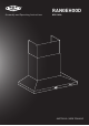
Assembly and Operating Instructions RANGEHOOD BRC214SA AUSTRALIA / NEW ZEALAND
CONGRATULATIONS CONTENTS Thank you for purchasing a Beefeater cooker hood. You’ve chosen a product that brings with it decades of professional experience and innovation. Ingenious and stylish, it has been designed with you in mind. So whenever you use it, you can be safe in the knowledge that you’ll get great results every time. Important safety instructions........................................................ 3 Welcome to Beefeater. Product description...............................................
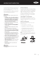
IMPORTANT SAFETY INSTRUCTIONS This manual explains the proper use of your new Beefeater canopy cooker hood. Please read this manual carefully before using the product. This manual should be kept in a safe place for handy reference. This cooker hood is a domestic appliance which has been manufactured and tested to comply with Australian and New Zealand Standard AS/NZS 60335.2.31 WARNING! Follow these instructions carefully to avoid an electric shock or fire.
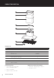
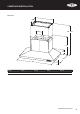
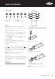
PRODUCT DESCRIPTION 1 2 3 4 5 6 7 8 Components list PART 1 Ceiling mount bracket 2 Upper flue cover 1 (427mm) 3 Lower flue cover 1 (500mm) 4 Wall bracket 1 5 Air outlet with non-return valve 2 6 Main body and fan housing assembly 7 Grease filters 6 8 Remote controller 1 2 fans Technical Specification Additional items required for installation • Power supply: 220~240 volts 50Hz Connects to 10A power point • Worm drive clamps, duct tape or cable ties • Ducting accessories
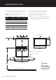
COOKER HOOD INSTALLATION Dimensions 630 403 ø200 780~1077 610 172 730 1220 60 MODEL WIDTH HEIGHT DEPTH WEIGHT BRC214SA 1200mm 780~1077mm 730mm 50.
COOKER HOOD INSTALLATION 1. Using a spirit level mark a vertical centre line on the wall where the cooker hood is to be positioned, and a horizontal line at the hood base position. * If the instructions of the cooker specifies a greater distance than the minimum height stated, then that shall be the minimum height for the installation NOTE: See table below for the minimum and maximum height of the underside of cooker hood. ** Installation height as specified in AS/NZS5601.
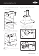
COOKER HOOD INSTALLATION 3. Install flue cover wall mounting brackets with suitable fixings. Install suitable screws for cooker hood mounting points (to support a total weight of 55kg) to the wall as marked. 5. U se cable ties or suitable duct tape to secure flexible pipe to the duct outlet. ø200mm 6. T he cooker hood can control the gas supply by controlling the solenoid valve. Unscrew those 4 screws to open the cover of connection box. 4.
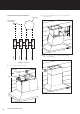
Circuit connection for gas solenoid valve: Solenoid valve 9. E nsure locking tab of lower flue cover is bent before installing covers. Wiring from rangehood 8. Insert power cord to power outlet. Power supply for solenoid To gas solenoid 8 COOKER HOOD INSTALLATION Grey Grey Brown Brown Power supply for solenoid valve 10. Slide telescopic flue cover to upper position and fix with screws provided.
USING THE COOKER HOOD Control operation 1 2 3 4 5 1 Lamp on/off 4 Speed 2 2 Delay end 5 Speed 3 3 Speed 1 6 Speed 4 (maximum) 6 1 2 33 4 5 6 Speeds Speed 1: Suitable for light frying and light barbecuing. Speed 2: Suitable for frying, wok cooking and barbecuing. Speed 3: Suitable for intensive frying, intensive wok cooking and barbecuing. You can also use the remote controller to control the cooker hood. The control method is the same.
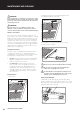
MAINTENANCE AND CLEANING WARNING! Before maintenance or cleaning is carried out, the cooker hood should be disconnected from the main power supply. Ensure the cooker hood is switched off at the wall socket and the plug removed. 2. Pull down the filter lock level and then pull the filter assembly down and out of the hood. WARNING! External surfaces are susceptible to scratches and abrasions, so please follow the cleaning instructions to ensure the best possible result is achieved without damage.
TROUBLESHOOTING GUIDE PROBLEM REMEDY The cooker hood will not start Check that cooker hood is connected to an electrical supply. Check that a fan speed has been selected. The cooker hood is not working Check that fan speed is high enough. Check that the grease filters are clean. Check that the kitchen is adequately vented to allow entry of fresh air. Check that ducting and outlets are not blocked.
TYPICAL INSTALLATIONS SHOWING ACCESSORY APPLICATIONS ROOF COWL ACCESSORY Some installations may require a vertical discharge cowl.
ACCESSORIES (200mm) 1 5 2 6 3 4 7 8 REF PART NUMBER DESCRIPTION 1 AR200FJ 200mm Flue joiner 2 AR200E 200mm 90 Elbow 3 AR200WV 200mm Wall vent 4 AR200WC 200mm Worm drive clamp 5 AR200FD 200mm Semi rigid flexible flue (0.7m min & 3.0m max length) 6 AR200F 200mm Flue (length 1200mm) 7 AR200RC 200mm Roof cowl 8 AR630FS Upper flue cover extension (1200mm) NOTE: Accessories are to be purchased separately.
NOTES 14 NOTES
Warranty FOR SALES IN AUSTRALIA AND NEW ZEALAND APPLIANCE: BEEFEATER RANGEHOODS Warranty This document sets out the terms and conditions of the product warranties for BeefEater Appliances. It is an important document. FOR SALES IN AUSTRALIA AND NEW ZEALAND Please keep it with your proof of purchase documents in a safe place APPLIANCE: BEEFEATER RANGEHOODS for future reference should there be a manufacturing defect in your Appliance.
For more information on all Beefeater products, or for dimension and installation information, call into your retailer, phone or email our customer care team or visit our website: AUSTRALIA phone: fax: email: web: 1300 307 939 1800 356 669 customercare@electrolux.com.au beefeaterbbq.com NEW ZEALAND phone: fax: email: web: 0800 436 245 0800 225 088 customercare@electrolux.co.nz beefeaterbbq.com Beefeater. We are part of the Electrolux Family.