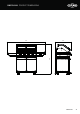
Assembly and Operating Instructions 7000 SERIES BMF7645SA,BMF7655SA BMG7642SA,BMG7652SA FOR OUTDOOR USE ONLY AUSTRALIA / NEW ZEALAND
CONGRATULATIONS CONTENTS Dear Customer, Important safety instructions.......................................................3 Congratulations and thank you for choosing our barbecue. We are sure you will find it a pleasure to use. Before you use the barbecue, we recommend that you read through the relevant sections of this manual, which provide a description of your appliance and its functions. BMF7645SA product description / dimensions ..........................
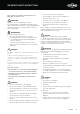
IMPORTANT SAFETY INSTRUCTIONS • Do not test for leaks with a naked flame • Do not modify the construction of this appliance or modify the injector orifice size • Do not place articles on or against this appliance Important – check for any damages or marks • Do not obstruct any ventilation of the barbecue If you find the barbecue is damaged or marked, you must report it within 7 days if you wish to claim for damage/marks under the manufacturer’s warranty. This does not affect your statutory rights.
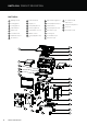
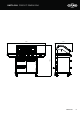
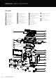
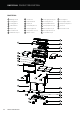
BMF7645SA PRODUCT DESCRIPTION BMF7645SA 1 Warming rack x2 9 2 Cooking grill x2 10 Drip tray x 1 17 Trolley mid panel assy x1 3 Cooking plate x1 11 Trolley back panel x1 18 Transformer x1 4 Flame tamer x2 12 Trolley top panel x1 19 Trolley left panel assy x1 5 Body assy x1 13 Trolley frame coross x1 20 Front door assy x1 6 Left side shelf x1 14 Rubber cover x2 21 Door hinge x2 7 Side burner assy x1 15 Trolley right panel assy 22 Door handle assy x1 8 16 Right reinforcing plate x1
BMF7645SA PRODUCT DIMENSIONS 708 1284 1602 DIMENSIONS 5
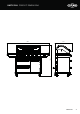
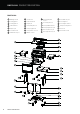
BMF7655SA PRODUCT DESCRIPTION BMF7655SA 1 Warming rack x 2 9 16 Right reinforcing plate x1 2 Cooking grill x2 10 Drip tray x1 17 Trolley mid panel assy x1 3 Cooking plate x1 11 Trolley back panel x1 18 Transformer x1 4 Flame tamer x 3 12 Trolley top panel x1 19 Trolley left panel assy x1 5 Body assy x1 13 Trolley frame cross x 1 20 Door assy x1 6 Left shelf x1 14 Rubber cover x2 21 Door Hinge x2 7 Right side table x1 15 Trolley right panel assy 22 Door handle assy x1 8 Oil foil
BMF7655SA PRODUCT DIMENSIONS 708 1284 1758 DIMENSIONS 7
BMG7642SA PRODUCT DESCRIPTION BMG7642SA 1 Warming rack x2 8 Oil foil box x1 2 Cooking grill x2 9 Foil box holder x1 Cooking plate x1 10 Drip tray x1 Flame tamer x2 11 Trolley back panel x1 Body assy x1 12 Trolley top panel x1 Left side shelf x1 13 Trolley frame coross x1 Side burner assy x1 14 Rubber cover x2 3 4 5 6 7 15 Trolley right panel assy x1 16 Door fixing stator x1 17 Trolley middle frame x1 18 Trolley left panel assy x1 19 Front left door assy x1 20 Front right door assy x2 2
BMG7642SA PRODUCT DIMENSIONS 685 1284 1602 DIMENSIONS 9
BMG7652SA PRODUCT DESCRIPTION BMG7652SA 1 Warming rack x2 8 Oil foil box x1 15 Trolley right panel assy x1 22 Door magnet x1 2 Cooking grill x2 9 Foil box holder x1 16 Door fixing stator x1 23 Door magnet stator x1 3 Cooking plate x1 10 Drip tray x1 17 Trolley middle frame x1 24 Trolley bottom panel x1 4 Flame tamer x2 11 Trolley back panel x1 18 Trolley left panel assy x1 25 Castors x2 5 Body assy x1 12 Trolley top panel x1 19 Front left door assy x1 26 Castor with lock x2 6 Le
BMG7652SA PRODUCT DIMENSIONS 1758 1284 685 DIMENSIONS 11
GAS SPECIFICATIONS Natural Gas Universal LPG BMG7642SA 1.85 1.10 BMG7652SA 1.85 1.10 BMF7645SA 2.05 1.11 BMF7655SA 2.05 1.11 Injector diameter-side burner BMG7642SA & BMG7652SA 1.87 1.15 Injector diameter-side burner BMF7645SA & BMF7655SA 2.4 1.35 Injector diameter-rear burner BMF7645SA & BMF7655SA 1.55 0.
BMF7645SA & BMF7655SA ASSEMBLY BMF7645SA BMF7655SA For BMF7645SA & BMF7655SA x60 M6 x 12mm x15 M4 x 10mm flat head x4 M4 x 10mm countersunk head Tools required: Phillips screwdriver Hexagonal screwdriver Wrench 19mm Wrench 22mm ASSEMBLING THE BARBECUE 13
BMF7645SA & BMF7655SA ASSEMBLY 1 Attach 4 castors The hole is at the back x 16 M6 x 12mm 26 25 26 27 Castor with locks at the front position 27 2 24 14 ASSEMBLING THE BARBECUE
3 4 19 18 ASSEMBLING THE BARBECUE 15
BMF7645SA & BMF7655SA ASSEMBLY 5 15 19 6 11 16 ASSEMBLING THE BARBECUE
7 11 8 ASSEMBLING THE BARBECUE 17
BMF7645SA & BMF7655SA ASSEMBLY 9 17 10 18 ASSEMBLING THE BARBECUE
11 12 13 16 ASSEMBLING THE BARBECUE 19
BMF7645SA & BMF7655SA ASSEMBLY 13 11 14 23 20 ASSEMBLING THE BARBECUE
15 20 22 16 21 ASSEMBLING THE BARBECUE 21
BMF7645SA & BMF7655SA ASSEMBLY 17 Assemble the front door Firstly, insert the upper and lower hook into the slots Then press down, when hear “pop”, the assembly is in place When connected, the upper and lower two tabs should be aligned with the rectangular slot When the hinge installed, turn this screw in counterclockwise, to level the front door 18 Disassemble the front door Then press the button Firstly turn the screw in clockwise for 1-2 complete turns Pull the the upper and lower two tabs out o
19 14 Electrical wires need to be kept outside, through the indicated hole 20 Spanner 19mm Spanner 19mm 5 ASSEMBLING THE BARBECUE 23
BMF7645SA & BMF7655SA ASSEMBLY 21 Recommend at least 2 people to lift. Due to the assembled body being a heavy lift Carefully locate the gas pipe into the hole of the trolley top panel 22 24 Assemble the transformer wires and the lighting wires, screw the connection to seal.
23 Insert the wires into the trolley to hide the wires 24 Disassemble the hose to easily access the screw hole ASSEMBLING THE BARBECUE 25
BMF7645SA & BMF7655SA ASSEMBLY 25 26 26 ASSEMBLING THE BARBECUE
6 7 28 ASSEMBLING THE BARBECUE 27
BMF7645SA & BMF7655SA ASSEMBLY 29 30 28 ASSEMBLING THE BARBECUE
31 Assemble side burner gas pipe to the manifold using 2 spanners 32 Connect the wires underneath the side burner ASSEMBLING THE BARBECUE 29
BMF7645SA & BMF7655SA ASSEMBLY 33 Locate the flame tamers: 2 flame tamers for 4 burners 3 flame tamers for 5 burners 4 34 3 2 Drainage holes are at the front 30 ASSEMBLING THE BARBECUE
35 Locate the warming rack 1 36 Sliding locked Sliding unlocked ASSEMBLING THE BARBECUE 31
BMF7645SA & BMF7655SA ASSEMBLY 37 10 38 9 32 ASSEMBLING THE BARBECUE
39 8 40 Spanner 19mm Spanner 22mm ASSEMBLING THE BARBECUE 33
BMF7645SA & BMF7655SA ASSEMBLY 41 Turn to lock the gas bottle tray Leak test procedure 34 • Ensure all gas valves are in the ‘OFF’ position. • In a small container, mix a solution of water and detergent or soap. • After connection of the hose, turn on the gas supply at the gas bottle. • Using a brush, apply the solution to all gas connection points and look for bubbles forming. • Bubbling will indicate a leak. • Turn off the gas supply and re-tighten the joint. Repeat the leak test.
42 Push down “ON” to brake Push down “OFF” to move 43 When moving the BBQ, it is necessary to raise the leveling foot, and at the same time, it cannot touch the fixed plate above, so as to avoid affecting the rotation of the wheels ASSEMBLING THE BARBECUE 35
BMG7642SA & BMG7652SA ASSEMBLY BMG7642SA BMG7625SA For BMG7642SA & BMG7652SA x55 x2 M6 x 12mm M4 x 10mm flat head x4 M4 x 10mm countersunk head Tools required: Phillips screwdriver 36 Hexagonal screwdriver ASSEMBLING THE BARBECUE Wrench 19mm Wrench 22mm
1 Attach 4 castors x 16 M6 x 12mm 25 The hole is at the back 24 25 Castor with locks at the front position 26 Castor with locks at the front position 26 2 22 23 ASSEMBLING THE BARBECUE 37
BMG7642SA & BMG7652SA ASSEMBLY 3 Assemble M6 head screw x6 , three on each side on the trolley bottom panel, do not fully tighten.
5 Assemble the back trolley panels with M6 head screws x7 11 11 ASSEMBLING THE BARBECUE 39
BMG7642SA & BMG7652SA ASSEMBLY 6 13 7 13 40 ASSEMBLING THE BARBECUE
8 Assemble the trolley top panel with M6 head screws x8 17 9 16 ASSEMBLING THE BARBECUE 41
BMG7642SA & BMG7652SA ASSEMBLY 10 Assemble the door handle assy: remove the screws from the handle then assemble the handle to door and fix with screws 21 19 20 11 21 19 42 ASSEMBLING THE BARBECUE
12 14 13 ASSEMBLING THE BARBECUE 43
BMG7642SA & BMG7652SA ASSEMBLY 14 15 44 ASSEMBLING THE BARBECUE
16 Align side burner gas pipe through the hole, pull wire through the hole 6 7 17 ASSEMBLING THE BARBECUE 45
BMG7642SA & BMG7652SA ASSEMBLY 18 19 46 ASSEMBLING THE BARBECUE
20 21 4 ASSEMBLING THE BARBECUE 47
BMG7642SA & BMG7652SA ASSEMBLY 22 3 2 Drip hole should be at front side 23 1 48 ASSEMBLING THE BARBECUE
24 25 10 ASSEMBLING THE BARBECUE 49
BMG7642SA & BMG7652SA ASSEMBLY 26 9 Put on the foil box holder onto the drip tray 27 Put the foil oil tray into the holder 8 50 ASSEMBLING THE BARBECUE
28 29 Push down “ON” to brake Push down “OFF” to move ASSEMBLING THE BARBECUE 51
BMG7642SA & BMG7652SA ASSEMBLY 30 When moving the BBQ, it is necessary to raise the leveling foot, and at the same time, it cannot touch the fixed plate above, so as to avoid affecting the rotation of the wheels 52 ASSEMBLING THE BARBECUE
NATURAL GAS INSTALLATION 1 Take out the warming rack, cooking plate and cooking grill 2 Disassemble the R latch NATURAL GAS INSTALLATION 53
NATURAL GAS INSTALLATION 54 3 Take out the burners 4 Change the injector size for the NG Version NATURAL GAS INSTALLATION
5 6 Unscrew the 6 M4 head screws from the rear burner cover Take out the front baffle plate and the rear burner cover NATURAL GAS INSTALLATION 55
NATURAL GAS INSTALLATION 56 7 Change the injector size 8 Unscrew the M5 head screws x2 from the side table NATURAL GAS INSTALLATION
9 10 Disassemble the side burner and change the injector for the NG version NATURAL GAS INSTALLATION 57
NATURAL GAS INSTALLATION 11 Change the injector size Spanner 19mm Spanner 22mm 12 Flexible hose outlet Spanner 22mm Tether connection point Spanner 19mm Mobile restraint with hose assembly. When the mobile barbecue is connected to a fixed gas supply via a flexible hose connection, a retaining tether of adequate strength shall be fixed to the appliance and be suitable to be fixed to the wall within 50mm of each connection point. The retaining tether must be less than 80% of the gas hose length.
INSTALLATION Partial Enclosures (Australia Only) This appliance shall only be used in an above ground, open air situation with natural ventilation, without stagnant areas, where gas leakage and products of combustion are rapidly dispersed by wind and natural convection.
RAIN BAFFLE INSTALLATION 1 BMG7642SA and BMG7652SA Remove the hood screw M4 x 10mm (flat head screw 4 PCS) 2 BMG7642SA and BMG7652SA Rain baffle Assemble the rain baffle: M4 x 10mm (flat head screw 4 PCS) 60 CONTENTS
RAIN BAFFLE INSTALLATION 1 BMG7645SA and BMG7655SA Remove the hood screw M4 x 10mm (flat head screw 4 PCS) 2 BMG7645SA and BMG7655SA Rain baffle Assemble the rain baffle: M4 x 10mm (flat head screw 4 PCS) CONTENTS 61
SIDE BURNER OPERATING INSTRUCTIONS Lighting Instructions LE ON 1. Do not attempt to light burner with the cooking surfaces covered 2. Read the instructions before lighting 3. To light burner depress knob and rotate to ‘HIGH’ 4. Keep knob pushed in for 5 seconds to ensure flame safety is activated (if fitted) 5. If burner did not light, turn knob to the ‘OFF’ position.
INSTALLATION WARNINGS Before You Begin Mobile Installation - Portable LP Gas/ Propane Check that the gas type is correct for your type of gas. Recommended minimum LPG/propane cylinder capacity for use with this appliance is 4kg. Maximum LPG/propane cylinder capacity for use with this appliance is 10kg. In the USA, only a 20lb cylinder may be used. You will find the gas type label on the side of your barbecue.
INSTALLATION WARNINGS Australia only (applies to all gas types) : Where a mobile appliance is to be connected to a fixed gas supply via a flexible hose connection, a retaining tether of adequate strength shall be fixed to the appliance and be suitable to be fixed to the wall within 50mm of each connection point. The length of the tether shall not exceed 80% of the length of the hose assembly. In this way, if the barbecue is accidentally moved, the chain stops the barbecue from stretching the hose.
GAS SPECIFICATIONS AND MOBILE RESTRAINT Turn down adjustment Secure all joints and leak test • When converting to natural gas the turndown setting will need to be adjusted to give a satisfactory flame on low setting on each burner. • Remove knob from valve shafts. For ignition valve the low flame adjustment screw is located on the lower right hand corner of the front of the valve body Never use a naked flame to check for gas leaks.
GAS SPECIFICATIONS AND MOBILE RESTRAINT Before you light the barbecue Lighting the barbecue Perform the following checks The same procedure is used to light the main burners as well as the side burner: • Make sure all gas connections are tight and leak tested • Ensure the cooking surfaces are clean and hygienic • Check the control knobs are in the off position • Check that the gas supply is turned on • Ensure the hood of the barbecue and the lid of the side burner are up.
Controlling The Burners After Use The control knob can now be turned to the desired heat setting, Low, Medium or High. The control knob does not need to be pushed in while selecting the heat setting. It is a good idea to leave the barbecue on for about 10 minutes after you have finished cooking. This helps to burn away any excess food residues and oil, and makes cleaning easier.
CARE AND MAINTENANCE This appliance should be checked and serviced by an authorised service person every 2 years to ensure the appliance remains in a safe operating condition. (These services are not covered by warranty). Spare parts are available from your retailer or the manufacturer.
MOUNTING ENCLOSURE GUIDELINES 630mm min. Separation panel 828mm 4 burner 100mm min. 40mm gap min. 540mm 930mm min.
OPERATING INSTRUCTIONS Control functions To turn the burners off Before lighting the barbecue: • When the cooking is complete, push the knob in and rotate clockwise back to the ‘OFF’ position • Check that all hoses and gas fittings are tight • Open the roasting hood Preheating • Check all control knobs are in the ‘OFF’ position • Ensure that the cooking surfaces are clean For best cooking results it is recommended to preheat the barbecue prior to cooking.
Reposition the grill plates You may find it useful to purchase a meat thermometer to help take the guess work out of cooking. To achieve the best heat circulation around the food, it is best to remove the hotplate from the barbecue and position the two grill plates in the centre. Reposition the vaporisers from above the 2 outside burners to above the inside burners. This will give unrestricted heat circulation from the 2 outside burners.
OPERATING INSTRUCTIONS The cleaning and care instructions are essential for the proper functioning and operation of your appliance over time. Failure to adhere to these care instructions may affect your ability to make a claim under the manufacturer’s warranty. Cleaning the Burners • Check main opening of burner regularly for insect nests (eg. wasp, ants or spiders). Nests are dangerous and must be cleaned out thoroughly.
TROUBLESHOOTING PROBLEM CAUSE CHECK Barbecue will not light Ignition system not working Check to see visible spark at starter probe - if no spark is present when control knob is turned then the unit may need to be serviced or replaced. Contact your BeefEater dealer. Check that there is a visible flame coming from the pilot ignition tube. Check that the pilot ignition tube is not blocked by spider webs or insect nests.
NOTES NOTES 74 NOTES
WARRANTY Warranty FOR SALES IN AUSTRALIA AND NEW ZEALAND APPLIANCE: BEEFEATER SIGNATURE BBQ, ALFRESCO KITCHEN This document sets out the terms and conditions of the product warranties for BeefEater Appliances. It is an important document. Please keep it with your proof of purchase documents in a safe place for future reference should there be a manufacturing defect in your Appliance. This warranty is in addition to other rights you may have under the Australian Consumer Law. 1.
Contact us if you need more help AUSTRALIA phone: 1300 307 939 email: customercare@beefeaterbbq.com web: beefeaterbbq.com NEW ZEALAND phone: 0800 436 245 email: customercare@electrolux.co.nz web: beefeaterbbq.com © 2022 Electrolux Home Products Pty Ltd.