Assembly and Operating Instructions FOR OUTDOOR USE ONLY 1600 SERIES TROLLEY MODELS BMG1641SA, BMG1651SA, BMG1641DA & BMG1651DA AUSTRALIA / NEW ZEALAND
CONGRATULATIONS CONTENTS Dear Customer, Important safety instructions................................................... 3 Congratulations and thank you for choosing our barbecue. We are sure you will find it a pleasure to use. Before you use the barbecue, we recommend that you read through the relevant sections of this manual, as well as the built-in manual to get a full understanding of your appliance and its functions. Product description..............................................................
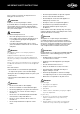
IMPORTANT SAFETY INSTRUCTIONS Please read the user manuals carefully and store in a handy place for later reference. WARNING IMPORTANT • Do not attempt to dismantle or adjust the regulator. • Do not test for leaks with a naked flame. • Do not modify the construction of this appliance or modify the injector orifice size.
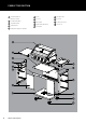
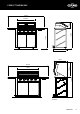
PRODUCT DESCRIPTION 1 4 burner barbecue 2 6 BMG1641 shown Brace 11 Side panel RH 7 Left hand side table Door LH 12 Door RH 8 Base panel 13 Locking castors x 2 9 Right hand side burner 14 Castors x 2 3 Separation panel 4 Side panel LH 5 Side panel support LH and RH 10 Rear panel 1 2 3 4 5 6 9 10 11 7 8 12 13 14 4 PRODUCT DESCRIPTION
PRODUCT DIMENSIONS 1670mm 926mm 1200mm 271mm 804.
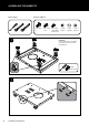
ASSEMBLING THE BARBECUE Tools required: Fasteners supplied: M6 x 10mm 47 1 M5 x 10mm 12 off M4 x 10mm 4 off (5 burner models only) 12 Fibre washers 1 x Oval grommet 1 x Circle grommet Important: ensure locking casters are fitted to the front of the trolley, with locks facing forward.
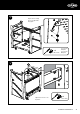
3 Repeat same assembly process on right hand side panel. 4 x screws for LHS panel x8 M5 x 10mm 4 x screws for RHS panel 4 Fit screws but do no tighten to position subsequent screws more easily.
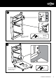
ASSEMBLING THE BARBECUE 5 Fit screws but do no tighten to position subsequent screws more easily. x2 M6 x 10mm 6 Fit screws but do no tighten to position subsequent screws more easily.
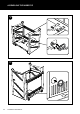
7 Repeat same assembly process on right hand hinge plate. 2 x screws for LHS panel x4 M5 x 10mm 2 x screws for RHS panel 8 x4 Tighten all screws to secure all panels.
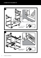
ASSEMBLING THE BARBECUE 9 10 10 ASSEMBLING THE BARBECUE
5 Burner model only x4 M4 x 10mm 12 x4 M6 x 10mm ASSEMBLING THE BARBECUE 11
ASSEMBLING THE BARBECUE 13 First fit lower door pin into the hole on the base assembly. Then depress the upper door pin with your finger, line up with the hole above on the separator panel, and release to allow the pin into the hole. 14 Remove the grease tray, then carefully lift the barbecue onto the trolley with two people, inserting the gas connector into the hole as shown.
15 Repeat same assembly process on right hand side. x2 x2 M6 x 10mm 16 Repeat same assembly process on right hand side. Refit the grease tray that was removed in step 14.
ASSEMBLING THE BARBECUE 17 18 Repeat same assembly process on right hand side.
19 Install the flame tamers above the burners that will be under a grill plate. See below for configuration.
ASSEMBLING THE BARBECUE 20 Install the solid plate and grill/s in one of the below configuration options, in order to keep the fat drainage hole from being placed directly above a burner. For easier installation, place the solid plate first, followed by the grill plates.
For 5 burner models: Option 1 For 5 burner models: Option 2 ASSEMBLING THE BARBECUE 17
ASSEMBLING THE BARBECUE 21 Plate and grill removal The plate and grill may be removed for cleaning following below steps: First lift up the grill from the centre edge as pictured, then remove the solid plate (and 2nd grill if fitted) for cleaning.
22 Connecting the side burner To connect the side burner: A Disconnect the gas hose and regulator assembly (A) from the barbecue using 2 spanners. 23 Connect the gas hose and regulator assembly (A) to the side burner connection using 2 spanners.
ASSEMBLING THE BARBECUE 24 Connect the gas hose (B) to the remaining connection on the side burner using 2 spanners.
26 WARNING IMPORTANT After completing the gas hose connections, conduct a leak test following the leak test procedure before using the appliance. WARNING WARNING To ensure gas tight connections, complete the gas leak test procedure before and after gas hose connection and after every reconnection of the gas cylinder. Failure to do so may result in a fire or explosion. Leak test procedure • • Ensure all gas valves are in the ‘OFF’ position. • Turn off the gas supply and re-tighten the joint.
SIDE BURNER OPERATING INSTRUCTIONS Control functions Manual lighting Before lighting the side burner: • In the event of the automatic ignition system not working, the barbecue can be lit manually • Position the manual igniter next to the burner.
GAS SPECIFICATIONS AND MOBILE RESTRAINT Gas Type Injector orifice diameter barbecue burner Natural Gas Universal LPG BMG1641SA 1.80 1.10 BMG1651SA 1.80 1.10 BMG1641DA 1.90 1.15 BMG1651DA 1.90 1.15 1.80 1.
NOTES NOTES 24 NOTES
NOTES NOTES NOTES 25
NOTES NOTES 26 NOTES
WARRANTY Warranty FOR SALES IN AUSTRALIA AND NEW ZEALAND APPLIANCE: BEEFEATER 1600 SERIES BBQ This document sets out the terms and conditions of the product warranties for BeefEater 1600 series BBQ. It is an important document. Please keep it with your proof of purchase documents in a safe place for future reference should there be a manufacturing defect in your Appliance. This warranty is in addition to other rights you may have under the Australian Consumer Law. 1.
For more information on all Beefeater products, or for dimension and installation information, call into your retailer, phone or email our customer care team or visit our website: AUSTRALIA phone: 1300 307 939 fax: 1800 356 669 email: customercare@electrolux.com.au web: beefeaterbbq.com NEW ZEALAND phone: 0800 436 245 fax: 0800 225 088 email: customercare@electrolux.co.nz web: beefeaterbbq.com BeefEater. We are part of the Electrolux Family.