
Manual

9/16 CC1B-Hints-en Preliminary 04.02.2003 HVAC Products
2. Hints
2.8 Setting up a standard temperature
application
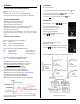
Using a 1000 ohm Ni RTD,
L & S # 556-541 –13 °F to +203 °F
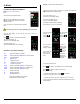
Configure
If no keys are pressed for 20 seconds, the controller will exit this
mode, and return to the basic display.
See Hint section 2.2, ‘How to configuration your RWF40”.
(From the basic display, or user level,
press
and hold, for 3 seconds,
and then release, and again,
press
and hold, for 3 seconds,
and then release)
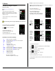
The actual value display, (9030)
shows the current configuration item value.
The setpoint display, (C111)
shows the configuration item you are adjusting.
The display is steady, (not flashing) and by default,
the 4
th
, (rightmost) digit may now be adjusted.
You can select which digit you wish to adjust, by
pressing
once and releasing it. The 3
rd
digit is now
flashing, indicating that it is now, the adjustable digit.
Cycle thru each digit of C111 and configure as charted
below, then accept by pressing
and releasing.
All four upper digits will flash once, and the new
configuration value, is displayed in 4 steady digits.
Press
and release, to configure C112, C113, … thru Df1.
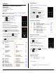
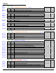
Configuration level values:
Item Description Value * Sec
C111 9000
Analog input 1 9 Landis & Staefa Ni 1000 8.1
Analog input 2 0 None 8.1
Analog input 3 0 None 8.1
D2 function 0 None 8.1
C112 8200 8.1
Limit comparator 8 input 1 8.1
Controller type 2 modulating 4-20mA 8.1
Setpoint SP1 0 via buttons 8.2
Locking 0 None 8.2
C113 0220
Unit address 02 Modbus address 8.2
Decimal - Units 2 (%) no decimals 8.2
Out-of-range Signal 0 limit comparator OFF 8.2
SCL SCale Low 0 Analog input 1 8.3.1
SCH SCale High 100 Analog input 1 8.3.2
SCL2 SCale Low 0 Analog input 2 8.3.3
SCH2 SCale High 100 Analog input 2 8.3.4
SPL SetPoint Low 160
limits low setpoint to 160 °F
8.3.5
SPH SetPoint High 205
limits high setpoint to 205 °F
8.3.6
OFF1 Actual value correction 0 Analog input 1 8.3.7
OFF2 Actual value correction 0 Analog input 2 8.3.8
OFF2 Actual value correction 0 Analog input 3 8.3.9
Df1 Digital filter time constant 0 Analog input 1 8.3.10
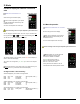
Set parameters
See Hint section 2.3, ‘How to adjust parameters’
The actual value display, (0)
shows the current parameter value.
The setpoint display, (AL)
shows the parameter item you are adjusting.
Increase
or decrease the value,
accept it by waiting 2 seconds.
Once it flashes, proceed to the next parameter
(HYSt) by pressing
and releasing.
Adjust all of the parameters as shown below.
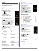
Parameter level values:
Value Item Description * Sec
160 AL Limit value for comparator 8.2
5 HYSt Switching differential for limit comparator 8.2
10 Pb.1 SPE setpoint external 9.2
80 dt Derivative time 9.2
350 rt Integral action time 9.2
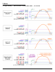
-5 HYS1
Burner-on 5 °F below setpoint
5.5.1
3 HYS2 Burner-off, 2-stage 5.2.3
5 HYS3
Burner-off 5 °F above setpoint
5.5.1
0 q Response threshold 5.6
1 H Heating curve slope 5.5.1
0 P Parallel displacement 5.5
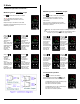
Set user level values
See Hint section3.4, ‘How to change a setpoint’.
You may enter the user level, directly from
the basic display.
Press
and release.
The actual value display, (180)
shows the current user level item value.
The setpoint display, (SP 1)
shows the user level item you are adjusting.
Increase
or decrease the value, accept it by
waiting 2 seconds. Once it flashes,
press
and release.
Adjust SP1 as shown below.
User level values:
V
alue Item Description * Sec
180 SP 1 Set point 1 .5.5.1
Setup is complete!
* Sec
Refers to the RWF40 user manual section.