
Boiler Guide


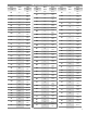


1. For your convenience, this guide is arranged
in alphabetical order by manufacturer.
2. Locate OEM name.
3. Locate Appliance Model Number.
4. Locate Burner Type (AF, AFG, SF...).
5. Locate Air Tube Combination. This will include:
A. Burner Model
B. Air Tube Length
C. Head Type
D. Static Plate
E. Special Construction. (See example below.)
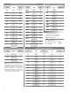
6. To identify the Special Construction Codes, turn
to the Air Tube Combination Code Listing pages.
7. Locate Specified Nozzle Selection.
8. Verify Pump Pressure.
9. Additional Information may include Notes that
give specific information regarding a particular
application. (See Note Column).
10.
*
Approximate Air Settings are given in some
applications. WARNING: These are approximate
air settings. The burner must be adjusted using
combustion test instruments for the final air setting.
Failure to do so could result in burner or appliance
failure, causing potential severe personal injury,
death or substantial property damage. Follow these
four steps to properly adjust the burner:
Step 1. Adjust air until a trace smoke level
is achieved.
Step 2. At the trace of smoke level, measure the
CO2 (or O2). This is a vital reference point for
further adjustments.
Step 3. Increase the air to reduce the CO2 by
1 to 2 percentage points. (O2 will be increased by
approximately 1.4 to 2.7 percentage points.)
Step 4. Recheck the smoke level. It should be zero.
11. Additional
Information
will help in selecting replacement
burner chassis.
• Locate OEM name and Appliance Model Number.
• Select Recommended Chassis replacement found
in Additional Information.
• Select recommended Air Tube Combination.
• Select recommended Nozzle.
• Look for specific “Notes” that may pertain to
a particular application.
• Follow Basic Burner Setup Information.
DANGER: All equipment must be installed, adjusted
and started only by a qualified service agency:
An individual or agency, licensed and experienced
with all codes and ordinances and with the latest
revision of the National Fire Protection Association
Standard NFPA31 or CSA B139-M91.
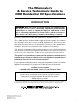
Instructions for Using
the Beckett OEM Specification Guide
Air tube is measured in usable length. The overall
length is 1/2” longer. The first digit is in inches, and
the second digit is in 1/8” increments.
(Example AF65 is 6-5/8”, and AF104 is 10-1/2”.)
1