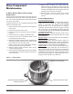
CORPORATION 24Vdc Oil Burner Manual Potential for Fire, Smoke and Asphyxiation Hazards Incorrect installation, adjustment, or misuse of this burner could result in death, severe personal injury, or substantial property damage. To the Homeowner or Equipment Owner: To the Professional, Qualified Installer or Service Agency: y Please read and carefully follow all instructions provided in this manual regarding your responsibilities in caring for your heating equipment.
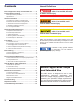
Contents Hazard Definitions Burner Application Scope and Intended Use ........... 2 Indicates a hazardous situation, which, if not avoided, will result in death or serious injury. Prepare Before Installing ............................................ 3 Notice Special Requirements.............................................3 Specifications .....................................................................3 General Information .................................................... 4 A.
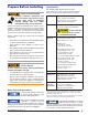
Section: Prepare Before Installing Prepare Before Installing Owner’s Responsibility Incorrect installation, adjustment, and use of this burner could result in severe personal injury, death, or substantial property damage from fire, carbon monoxide poisoning, soot or explosion. Contact a professional, qualified service agency for the installation, adjustment and service of your oil heating system.
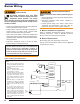
Section: General Information Adequate Voltage Required A low or erratic power supply could result in impaired burner operation, severe delayed ignition or an explosion inside the heat exchanger resulting in a burn and/or asphyxiation hazard. y The Model ADC requires a continuous supply of 21.6 to 28 volts DC measured at the burner during operation with a minimum supply & circuit capacity of 15A. See page 3 for maximum capacity and voltage specifications.
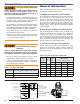
Section: Nozzle Assembly Maintenance D. Exhausting Hazardous Fumes See warning on this page. Also be conscious of any fumes produced by the materials that are being heated. Always ensure adequate ventilation to exhaust all fumes. E. Low Firing Rate Baffle. The low firing rate baffle (See LFRB in Replacement Parts) reduces the air flow and pressure. The LFRB is sometimes used for firing rates under 1.00 gph as listed in Table 1. Refer to the equipment manufacturer’s instructions.
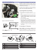
Section: Nozzle Assembly Maintenance The igniter must be grounded to the burner before checking the following. To check the igniter, ensure all power to the burner is off and use an ohmmeter to check the resistance between the two springs. The meter should read between 480 - 580 ohms. Figure 3. Igniter Hinge & Retainer Clips The igniter should be replaced if the meter indicates an open circuit, or the spring-to-spring resistance exceeds the 480 - 580 ohms range by more than 10%.. a c D.
Section: Fuel Supply tube installed but should always be verified during service and installation. If the “Z” dimension is out of adjustment, perform the following steps. Before proceeding, turn off power to the burner. 1. Disconnect the oil connector tube from the nozzle line. 2. Referring to Figure 5, loosen the splined nut from the nozzle line. Loosen the hex head screw securing the escutcheon plate to the burner housing. 3. A Beckett T650 gauge should be used to set the Z dimension. 4.
Section: Burner Wiring Burner Wiring Explosion, Fire, Scald, & Burn Hazard Electrical Shock Hazard All heating equipment must have HIGH LIMIT controls to protect against excessive temperature and/or pressure. The control must interrupt electrical power and shutdown the burner, if operating or safety controls fail and cause a runaway condition. y Follow the equipment manufacturer’s wiring diagrams and note all required safety controls.
Section: Drive Component Maintenance Drive Component Maintenance A. Motor, Blower Wheel, and Coupling Replacement The motor will require replacement if the proper voltage is measured at the motor input, and the motor will either not run, or the current draw with a free running pump exceeds 10% of the rated current. To replace the burner motor, coupling and/or blower wheel perform the following steps. 1. Before servicing, turn off and/or disconnect all power to the burner. 2.
Section: Drive Component Maintenance C. Valve Coil and Stem Replacement To determine if the valve coil requires replacement perform the following steps. 1. Remove the cord set from the valve. 2. Place the leads from an ohmmeter across the coil. 3. A 24Vdc volt coil should measure between 60 and 75 ohms. 4. If the meter indicates an open circuit, replace the coil. To check pump operation perform the following. 1.
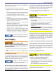
Section: Start Up Burner & Set Combustion Start Up Burner & Set Combustion A. Basic Burner Operation With 7559 Control - The 7559 control provides the benefits of added safety, convenience, and performance. It adds a valve on delay and motor-off delay to the burner’s operation sequence that promote clean burner operation. It has a lock-out function that shuts the burner down if it is not operating properly. The control adds fusing at the burner to protect against component failures.
Section: Maintain & Service Burner Maintain & Service Burner A. Owner’s Information Professional Service Required Incorrect installation, adjustment, and use of this burner could result in severe personal injury, death, or substantial property damage from fire, carbon monoxide poisoning, soot or explosion. Please read and understand the manual supplied with this equipment.
Section: Troubleshooting □ Clean the cad cell, if applicable. Table 3. Nozzle Flow Rate by Size □ Make sure Low Firing Rate Baffle is in place, if required, for the burner application. Omitting the baffle can result in unacceptable burner combustion. □ Inspect all gasket including the igniter base plate gasket. Replace any that are damaged or missing. □ Clean the blower wheel, air inlet, air guide, retention head and static plate of any dirt, asphalt or other material. □ Check motor current.
Section: Troubleshooting Table 4. Troubleshooting Chart Symptom Possible Cause If the burner is not igniting, the burner motor, drive coupling, and oil pump are operating and oil is flowing to the nozzle through the solenoid valve, check the following possibilities. Oil Not Igniting 1. Check the air shutter adjustment. If the air shutter is opened too far, the flow of air may prevent the arc from reaching the oil spray. This may appear as a white vapor exhaust from the heater.
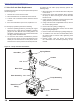
Section: Replacement Parts Replacement Parts 21 20 23 22 19 17 15 18 16 13 10 12 14 1 11 4 8 9 6 7 Illustration # Description Part# 1 DC Motor 21773U 2 Blower Wheel 2999U 3 2 5 Illustration # Description Part# 13 Escutcheon Plate Spline Nut 3666 14 Escutcheon Plate 3493 578731 3 Coupling 2140501 15 Electrode Kit over 3-5/8” 4 Air Guide 31231U 16 Cad Cell Detector 7492/7006U 5 Burner Housing - Black 5874BKU 17 Igniter Gasket Kit 51411 6 Air Band 5151501
Limited Warranty Information The R. W. BECKETT CORPORATION (“Beckett”) warrants to persons who purchase its “Products” from Beckett for resale, or for incorporation into a product for resale (“Customers”), that its equipment is free from defects in material and workmanship. To qualify for warranty benefits, products must be installed by a qualified service agency in full compliance with all codes and authorities having jurisdiction, and used within the tolerances of Beckett’s defined product specifications.