
Operating instructions


6
Assembly and Operating Instructions
5
6
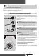
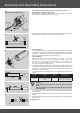
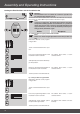
3. Before tting in the barrel, take the measurement from barrel end to the
centre of the drive adapter and mark on the barrel (Fig. 5).
• For prole tubes:
For some drive adapters, tolerances of the channel widths in different
roller tubes can be balanced by turning the drive adapter in a different
channel slot. These channel slots come in different sizes and make it an
exact t possible when the drive is installed (Fig. 6).
• For round tubes:
Release the tube from the motor died in advance, so that the
cam of the ring can also be inserted into the tube. The cam of
the ring must not engage with the tube. For rings without pull-
ing cams, the roller tube must be connected to the ring by a
4.8 x 10 mm sheet-metal screw (Fig. 7).
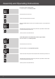
4. Assemble the tubular drive with the relevant ring (A) and drive adapter (B).
Insert the tubular drive with the pre-assembled ring and drive adapter into
the tube as shown. Ensure that the ring and drive adapter are correctly
positioned in the tube. (Fig. 8)
The drive adapter of the tubular drive is connected to the roller tube as
follows:
Attention
When drilling into the roller tube, never drill near the tubular
drive!
The tubular drive must not be hit into the tube or dropped into
the roller tube!
The drive manufacturer also recommends screwing the thrust bearing to
the roller tube.
5. Hang the tube in the bracket and secure the motorhead piece in the drive
bracket.
6. Hang the mounted unit consisting of tube, tubular drive and thrust bracket
in the bracket.
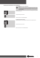
Cabling (Fig. 9)
Size of drive
[mm]
Roller shutter tubes–Ø
[mm]
Torque max.
[Nm]
Fastening screws
for drivers (4 x)
Ø 45
60 - 70 mm
plastic or diecast drive
adapter
50
at-headed sheet-metal
screw ST 6.3 x 10 DIN 7982
4
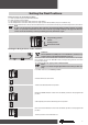
• Assembly of the drive adapter with screw connection for the
R30/17C PR+ to R40/17C PR+ drives:
Here the drive is xed with an M6x12 screw. It is secured with a plain wash-
er for M6 and a suitable toothed washer (Fig. 4).
R30/17C PR+ to R40/17C PR+
8
7
9