
Operating instructions

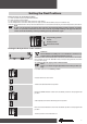

5
2
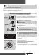
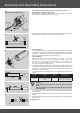
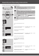
Assembly of the Becker connecting cable (Fig. 1)
Ensure the Becker connecting cable is de-energised before proceeding. In-
sert the cable into the drive head until the location lug audibly engages behind
the self-locking clip. If necessary, use a suitable at-bladed screwdriver to
insert the cable correctly. This is done by inserting the screwdriver into one of
the two recesses in the connector.
Check the locking.
Disassembly of the Becker connecting cable (Fig. 1)
Caution
Always completely de-energise the Becker connecting cable
prior to disassembly.
1. Carefully insert a suitable at-bladed screwdriver into the recess of the
self-locking clip until it releases the location lug of the connecting cable.
2. It is now possible to carefully withdraw the Becker connecting cable along
with the at-bladed screwdriver.
Caution
Electrical connections may only be carried out by a qualied
electrician. Prior to assembly, the power supply should be
disconnected. Please give the enclosed connection informa-
tion to the electrical tter carrying out the work.
Prior to mounting, the tter must ensure that the masonry and the shutter box
are sufciently robust (drive torque plus weight of the shutters).
Attention
Drives from Becker Antriebe are to be mounted and operated
solely with mechanical accessory components shown in the
current Becker product catalogue.
1. Establish the room required at the side for mounting (M) of the head piece,
thrust bracket and motor bracket , in order to calculate the required length
of roller tube. The internal dimension of the roller shutter box (X) minus the
overall length of wall bracket+head piece (M) and thrust bracket (T) gives
the length (L) of the roller tube:
L=X-(T+M) (Fig. 2).
Measure the distance from the wall bracket and connecting head since
this can vary according to the combination of motor and bracket.
2. Then x wall and thrust bracket.
Please observe the following when assembling the drive:
• Assembly of the drive adapter with locking device for the
R8/17C PR+ to R20/17C PR+ drives:
You can see how to insert the locking device from its shape. When insert-
ing the locking device, ensure that the catch locks into place. You will hear
a click. Check that the locking device is in position properly by pulling on
the drive adapter (Fig. 3).
Mounting and installation instructions
3
R8/17C PR+ to R20/17C PR+
1
2.
1.
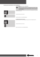
Location lug
Click
Self-locking clip
Attention
Anti-lifting devices may only be used if sufciently rigid roller shutter laths are used. When closed, the
shutters must not extend over the guide rails, as this may put too great a load on the joint between the top
two slats, which could consequently be damaged.
Before reaching the lower end limit, the roller shutters must have made at least 1.5 revolutions. This is normally the case when
the window height is ve times the effective tube diameter.
Example:
60-series octagonal tube with anti-lifting device from Zuruh-Feller:
Effective tube diameter: 9 cm -> min. window height > 45 cm