R8/17C PR+ - R40/17C PR+ en Assembly and Operating Instructions Tubular drives for roller shutters Wi th plu Ne w co g g : nn a b ec tin le B g c eck ab er le Important information for: • Fitters • Electricians • Users Please forward accordingly! These instructions must be kept for future reference. Becker-Antriebe GmbH 35764 Sinn/Germany www.becker-antriebe.
Assembly and Operating Instructions Table of Contents General....................................................................................................................................................................... 2 Warranty...................................................................................................................................................................... 3 Safety Information......................................................................................
Warranty Structural modifications and incorrect installation which are not in accordance with these and our other instructions can result in serious injuries, e.g. crushing of limbs. Therefore, structural modifications should only be carried out with our prior approval and in accordance with our instructions, particularly the information contained in these Assembly and Operating Instructions. Any further processing of the products which does not comply with their intended use is not permitted.
Assembly and Operating Instructions • • • • • • • • • • • • • • • • • • • • Important safety instructions for the installation and commissioning Caution! Failure to observe these instructions can lead to serious injuries. Please comply with the safety instructions EN 60335-2-97. Please note that these safety instructions cannot be assumed as being complete, since this standard does not consider all the possible causes of risk.
Attention Anti-lifting devices may only be used if sufficiently rigid roller shutter laths are used. When closed, the shutters must not extend over the guide rails, as this may put too great a load on the joint between the top two slats, which could consequently be damaged. Before reaching the lower end limit, the roller shutters must have made at least 1.5 revolutions. This is normally the case when the window height is five times the effective tube diameter.
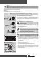
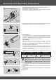
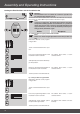
Assembly and Operating Instructions 4 • Assembly of the drive adapter with screw connection for the R30/17C PR+ to R40/17C PR+ drives: Here the drive is fixed with an M6x12 screw. It is secured with a plain washer for M6 and a suitable toothed washer (Fig. 4). 5 3. Before fitting in the barrel, take the measurement from barrel end to the centre of the drive adapter and mark on the barrel (Fig. 5).
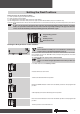
Setting the Final Positions There are 4 ways to set the final positions: a) Lower position to upper position without buffer b) Lower position to upper buffer c) Anti-lifting device at the lower final position to upper buffer d) Anti-lifting device at the lower final position to upper position without buffer (only via installation set) The final limit position becomes fixed, after the tubular drive has turned off automatically, in the desired position, three times.
Assembly and Operating Instructions b) Lower position to upper buffer Push both buttons to the delete position. Actuate a brief start command. Travel to the desired lower final position. Move the DOWN direction switch from the delete position to the programmed position. Subsequently travel upwards against the permanent upper buffer until the tubular drive automatically switches off. The final positions have now been set.
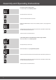
Deleting the Final Positions via the Switches a) Deleting the final positions individually Note It is only possible to delete an individual final position if lower position to upper position without buffer has been programmed via the switches. Move the switch of the respective final position from the programming position to the delete position. Actuate a brief start command. The final position has now been deleted.
Assembly and Operating Instructions Setting the Final Positions via the Installation Set Attention The installation set is not suitable for continuous operation and has only been designed for set-up. Connect the wires of the tubular drive to the same coloured wires of the installation set (Art. No. 4935 200 011 0) and switch on the mains supply.
Action Response c) Anti-lifting device at the lower final position to upper buffer Move both switches to the programming position. Travel downwards until the lower final position. The tubular drive switches off automatically. Subsequently travel upwards against the permanent upper buffer. The tubular drive switches off automatically. The final positions have now been set.
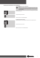
Assembly and Operating Instructions Deleting the final positions via the installation set Action Response a) Deleting one final position if two final positions have been programmed Travel to the final position which is to be deleted. 1. Press the reset button (1) 2. Additionally press and hold the downward button (2). 3. Now release the reset button (1), but keep the downward button (2) pressed. clack 4. Additionally press the reset button (1) again.
Information for the Electrician Becker tubular drives with electronic limit switching can be parallel connected. The maximum switching contact loading of the control device (timer, relay control, switch, etc.) must be observed. Use external conductor L1 to control the up and down direction. Other devices or consumption units (lamps, relays, etc.) must not be directly connected to the drive connection cables. For this purpose, the drives and additional units must be decoupled by relay controls.
Assembly and Operating Instructions What to do if...? Problem Tubular drive overruns the end limit or does not reach the set end limit.. Remedy 1. Investigate source, dry out the system and reprogramme. 2. External devices are connected to the power 2. Check electrical installation, remove exleads of the tubular drive. ternal device if connected, reprogramme system. 3. L1 and N connection have been reversed. 3. Exchange L1 and N (N = blue, L1 = black/ brown), reset the end limits. 4.
Sample wiring diagram Electronics Green-Yellow Blue Brown Black Electronics Controlling one/several drive(s) via a single switch/button Individual switch Subject to technical changes without notice 15
Assembly and Operating Instructions Brief instructions commissioning PR+ Caution Always adhere to the information contained in the assembly and operating instructions during commissioning, operation and repair work. The manufacturer or supplier shall not accept liability for personal injuries, property damage or consequential damages resulting from non-adherence to the instructions. Setting the final positions via the switches 1. Deleting both final positions Set both switches to .