
Operating instructions


7
7
6
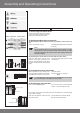
4. The drive adapter of the tubular drive is connected to the roller tube as fol-
lows:
Size of drive
[mm]
Roller shutter tubes–Ø
[mm]
Torque max.
[Nm]
Fastening screws
for drivers (4 x)
Ø 45
60 - 70 mm
plastic or diecast drive
adapter
50
Self-tapping screw
Ø 4.8 x 9.5 mm
The drive manufacturer also recommends screwing the thrust bearing to the
roller tube.
Attention
When drilling the roller tube do not drill in the area around the
tubular drive! The tubular drive must be inserted carefully into
the tube. It should not be hammered or simply dropped into the
tube! The shutters can be secured using springs or anti-lifting
devices only.
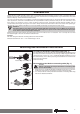
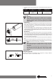
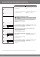
• Prole tubes:
Attach a suitable limit ring adapter (A) and drive adapter (B) to the tubular
drive. After having done so, slide the drive into the tube so that it engages
positively. When doing so, ensure that the limit ring adapter and drive adapt-
er t securely into the tube.
For some drive adapters, the slot width tolerances of different roller tubes
can be compensated by turning the drive adapter into another slot recess.
These slot recesses have different dimensions and allow you to mount your
drive accurately (Fig. 6).
• Round tubes:
Release the tube at the motor end to allow the cam of the limit ring adapter
to be slid into the tube. There must be no clearance between the cam of
the limit ring adapter and the tube. For limit ring adapters without locating
cams the roller tube must be connected to the limit ring adapter using a
4.8 x 10 mm tapping screw (Fig. 7).
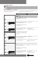
5. Insert the tube into the bearing and secure the motor end in the drive bear-
ing.
6. After the transmitter programming, position the roller tube such that the roll-
er shutters can be secured with springs. Alternatively, install the anti-lifting
lock in accordance with the manufacturer’s stipulations.
Note
When using springs we recommend that at least 3 are used;
For longer roller tubes 3 springs are to be used per meter of
roller tube.
Install motor connecting cable to the tubular drive in ascend-
ing direction and secure. The motor cable and the antenna
must be well clear of the winding space. Sharp edges must be
covered.
Cabling (Fig. 8)
Acknowledgement
The roller shutter drive acknowledges every programme, setting or deletion
process with a “clack” or “clack-clack” sound.
8