
Operating instructions

6
Assembly and Operating Instructions
3
5
Mounting the roller shutter drive
Attention
Drives from Becker Antriebe are to be mounted and operated
solely with mechanical accessory components shown in the
current Becker product catalogue.
Prior to mounting, the tter must ensure that the masonry and the shutter box
are sufciently robust (drive torque plus weight of the shutters).
Caution
These drives may not be operated with conventional switching
elements (switches, timers or similar).
If the roller shutters are to be operated in the opposite direc-
tion to the upper stopper, the shutters must be stopped from
being wound up into the shutter box by stoppers or by a right-
angled end slat. We recommend tting covered stoppers into
the guide rails prior to mounting.
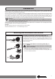
1. The lateral spatial requirements (M) for the box end, the counter bearing
and the motor bearing must be determined in order to calculate the required
length of the roller tube. The length (L) of the roller tube is equal to the clear
dimensions of the roller shutter box (X) minus the total length of the wall
bracket, box end (M) and counter bearing (G): L=X-(G+M) (Fig. 2).
Measure the distance from the wall bracket and connecting head as this
may vary depending on the drive and bearings used.
2. Secure the wall bracket and the counter bearing.
Attention
If anti-lifting devices are being used, closed bearings must be
used. When the shutters are closed, the tubular drive pushes
the shutters downwards to prevent them from being raised or
forced open. Always use suitably robust shutters, for example
made of aluminium, steel or wooden. To prevent the shutters
from being damaged the entire shutter must run in guide rails.
To install the drive, the following instructions must be followed carefully:
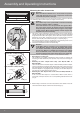
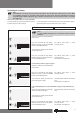
• Removing the mounting pin
The mounting pin engages automatically when inserted. To remove the
mounting pin slide the bearer plate upwards and pull out the mounting pin
(Fig. 3).
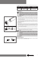
• Mounting the drive adapter with safety catch R8/17C PRF+ to
R20/17C PRF+:
The insert direction for the drive adapter is determined by the drive adapter
type (shape). When inserting the drive adapter with safety catch ensure that
the catch engages with the location lug. You will hear a clicking sound when
the drive adapter has engaged properly. Pull lightly on the drive adapter to
ensure that it has been tted securely (Fig. 4).
• Mounting the drive adapter with screw connection R30/17C PRF+ to
R40/17C PRF+:
In this case the drive adapter is fastened with a M6x12 screw, which is
secured by a M6 plain washer and a corresponding toothed lock washer
(Fig. 4).
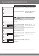
4
Self-locking hole
Location lug
Drive adapter with safety catch
Drive adapter
Drive adapter
Tapped hole
M6x12 screw
Toothed lock washer
Plain washer
R8/17C PRF+ to R20/17C PRF+
R30/17C PRF+ to R40/17C PRF+
2
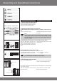
3. Before tting in the barrel, take the measurement from barrel end to the
centre of the drive adapter and mark on the barrel (Fig. 5).