
Operating instructions

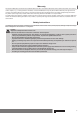

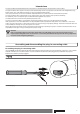
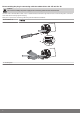

Table Of Contents
- Front cover
- Table of contents
- Contents
- General
- Warranty
- Safety instructions
- Intended use
- Assembling and disassembling the plug-in connecting cable
- Installation
- Assembling the drive
- Undoing the mounting pin
- Drive adapter for obstacle detection
- Assembling the drive adapter with drive adapter safety catch
- Assembling the drive adapter with screw connection
- Securing the drive against axial displacement
- Fixing the drive adapter to the barrel dia. 45
- Mounting the drive in the tube
- Confirming the drive
- First operation
- Programming the master transmitter
- Checking that the running direction is correct
- Intelligent installation management
- Setting the limit positions
- Changing the set limit positions
- Deleting the limit positions
- Intermediate positions I + II
- Programming additional transmitters
- Deleting transmitters
- Overwriting the master
- Upper anti-freeze mechanism
- Obstacle detection
- Fly screen protection function
- Programming the run times
- Deleting the run times
- Disposal
- Maintenance
- Technical data dia. 45
- What to do if...?
- Sample wiring diagram
- Declaration of conformity
- Last page
Installation
Assembling the drive
Attention
To connect the drive to the driven part, solely mechanical accessory components made by the drive manufac‐
turer from the current product catalogue may be used.
Prior to mounting, the fitter must ensure that the masonry and the system being motorised are sufficiently robust (drive torque plus
weight of the shading solution).
Caution
Electrical connections may only be carried out by a qualified electrician. Prior to assembly, the power supply
must be disconnected and secured. Please give the enclosed connection information to the responsible elec‐
trical contractor.
These drives cannot be operated with conventional switching elements (switches, timers and the like).
If you want the roller shutter curtain to open to the upper stop, proceed as follows: The roller shutter curtain
must be prevented from being drawn into the shutter box with a mechanical stop or an angled end strip. With
face-fixed elements, we recommend concealed stops in the guide tracks.
Calculate the space required at the side (M) by measuring the drive head and wall
bracket. The clear dimension of the box (X) minus the space required at the side (M)
and idler (G) gives the length (L) of the barrel: L=X-M-G.
The space required at the side (M) varies depending on the combination of drive and
wall bracket.
Then mount the wall bracket and idler. Ensure that the barrel is aligned at right angles to the wall and that sufficient axial play is
allowed for the mounted system.
Attention
When using anti-lifting devices, closed brackets must be fitted. The tubular drive presses the closed curtain
down to make it difficult for people to reach under it or raise it. Only use curtains made of sufficiently strong
material, such as aluminium, steel or wood. To prevent damage to the curtain it must run in guide tracks from
top to bottom.
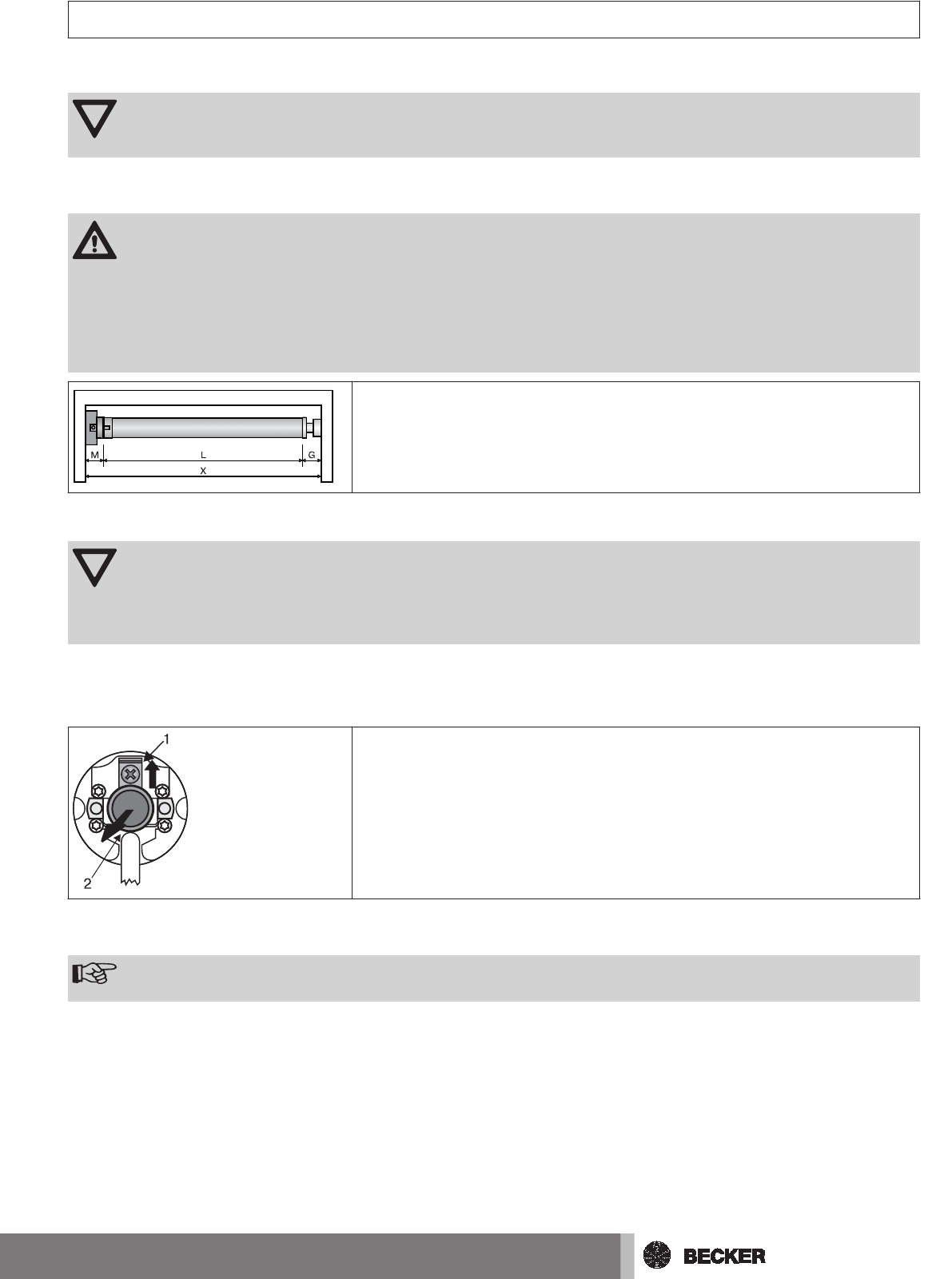
Undoing the mounting pin
When pushed in, the mounting pin (2) locks automatically. To undo the mounting pin
(2), push the tab washer (1) upwards and pull out the mounting pin (2).
Drive adapter for obstacle detection
Note
If you wish to use the "obstacle detection" function, you must use the "drive adapter for obstacle detection".
9